

Cement Plant Parts
Rotary Kiln Parts | Tyres Rollers & Castings | ATF
Kiln tyres support rollers thrust rollers nose rings. Heat-resistant alloy steel & cast iron. Factory-direct pricing. Quote in 24 hours.
Rotary Kiln Components for Cement Manufacturing
Cement rotary kilns are the heart of clinker production — operating at burning zone temperatures up to 1,450°C while rotating continuously at 1–5 RPM for years between major overhauls. Kiln tyres (riding rings), support rollers, thrust rollers and nose ring castings must withstand enormous combined thermal and mechanical loads. Tyre contact stresses reach 50–100 MPa at shell temperatures of 250–350°C, while nose rings face direct exposure to incandescent clinker at 1,100–1,400°C.
ATF manufactures kiln tyres from cast steel (G20Mn5) for standard duty and forged alloy steel (42CrMo4) for heavy-duty applications, with support rollers ground to controlled crown profiles and optionally induction-hardened to 50–55 HRC. Nose ring castings use HK40 and HP40 heat-resistant alloys rated for continuous service at 1,000–1,100°C. All steel components are supplied with material test certificates per EN 10204 Type 3.1, with NDT as specified — supporting the 330+ days/year production targets that cement plant economics demand.
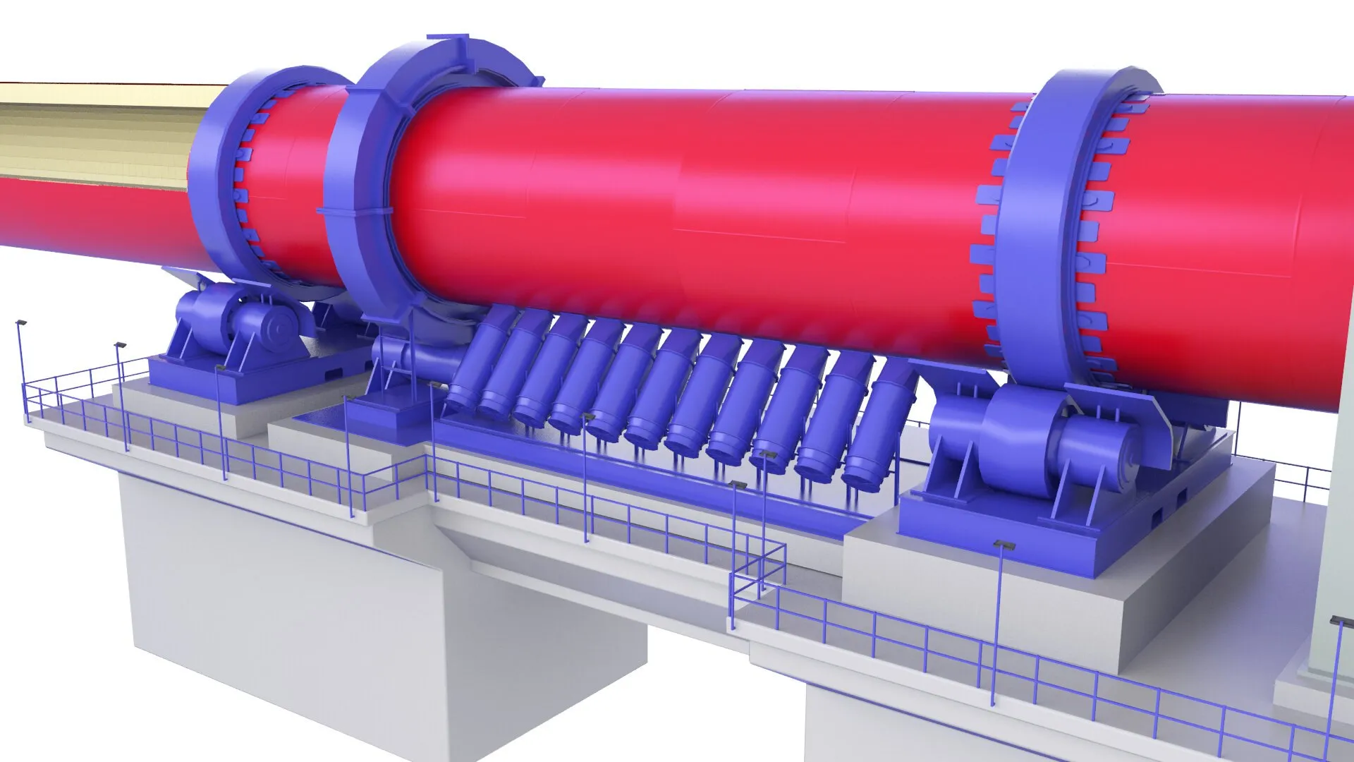
ATF rotary kiln components — kiln tyres, support rollers, thrust rollers and nose ring castings engineered for continuous high-temperature cement production.
How Cement Rotary Kilns Work
Understanding the thermal, mechanical and geometric demands on kiln components explains why material selection, precision machining and alignment are critical to achieving the continuous production that modern cement plant economics require.
Kiln Rotation & Support
The kiln is a long steel cylinder (3.0–6.2 m diameter, 50–100 m length) inclined at 3–4% and rotating at 1–5 RPM. The kiln’s mass — often 1,000–3,000 tonnes including refractory — is supported on 2 or 3 tyre (riding ring) stations, each resting on a pair of support rollers. The tyres transfer the gravitational and dynamic loads to the rollers, which transmit them to the foundations. Thrust rollers control axial migration. Every contact surface must maintain precise geometry under continuous thermal and mechanical loading.
Clinker Formation
Preheated raw meal enters the kiln feed end and travels downward by gravity and kiln rotation through progressively hotter zones: drying (up to 200°C), calcining (600–900°C), transition (900–1,250°C) and the burning zone (1,250–1,450°C) where calcium silicates combine to form clinker nodules. Fuel (coal, gas, petcoke or alternative fuels) is fired from the kiln discharge end, creating a flame that heats the material through radiative and convective heat transfer. The refractory lining protects the shell from these extreme temperatures.
Discharge & Component Stress
Incandescent clinker (1,100–1,400°C) drops from the kiln discharge end past the nose ring into the clinker cooler. The nose ring operates under the most extreme thermal conditions in the entire kiln — direct radiative heat from the flame, contact with falling clinker, and thermal cycling from kiln rotation. The kiln shell expands thermally during operation (up to 200 mm axially), and tyre designs must accommodate this expansion while maintaining support geometry. All mechanical components experience continuous fatigue loading from rotation.
Rotary Kiln Mechanical & Wear Components
ATF manufactures the complete range of rotary kiln structural and wear components for cement kilns from 3.0 m to 6.2 m diameter. Each component requires specific material selection, heat treatment, precision machining and quality documentation.
Kiln Tyres (Riding Rings)
Massive cast or forged steel rings that transfer the kiln’s rotating mass to the support roller stations. Tyres operate under contact stresses of 50–100 MPa at shell temperatures of 250–350°C, rotating continuously for 20–30 years between replacements. Cast steel (G20Mn5) for standard duty; forged alloy steel (42CrMo4) for heavy-duty and high-load applications. Available as solid rings or sectional designs for field assembly.

Support Rollers
Precision-ground rollers that carry the kiln’s entire rotating mass at each support station. The roller crown profile must be precisely matched to the tyre running surface to ensure correct load distribution across the full contact width — incorrect profiles cause edge loading, surface fatigue and premature failure. Forged 42CrMo4 steel with optional induction hardening to 50–55 HRC on running surfaces.
Thrust Rollers
Axial restraint rollers that control kiln migration (axial movement) along its inclined axis. Thrust rollers absorb the continuous downhill force generated by kiln inclination (typically 3–4% slope) and thermal expansion of the shell. Hardened contact surfaces and heavy-duty bearings handle continuous thrust loads while allowing controlled axial float to accommodate thermal cycling.
.Df70fKqF_2gfOYX.webp)
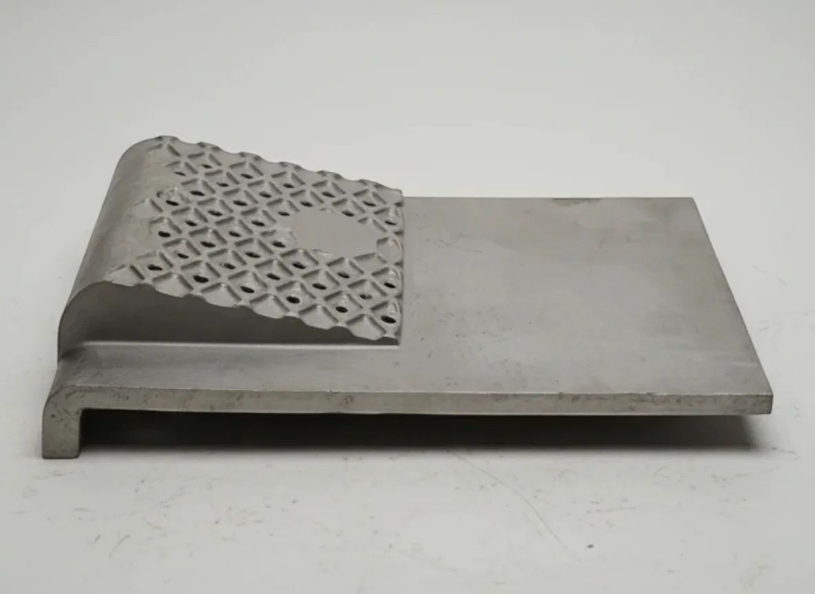
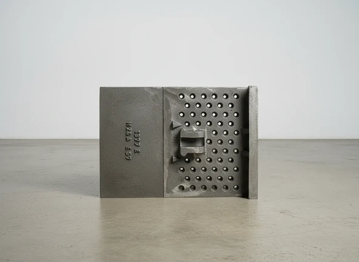
Nose Ring Castings
Segmented heat-resistant castings protecting the kiln discharge end where clinker at 1,100–1,400°C exits the burning zone. Nose rings face the most extreme thermal and abrasive conditions in the kiln — direct contact with incandescent clinker, radiative heat from the flame, and thermal cycling from kiln rotation. HK40 (25Cr-20Ni) and HP40 (25Cr-35Ni) alloys rated for continuous service at 1,000–1,100°C.
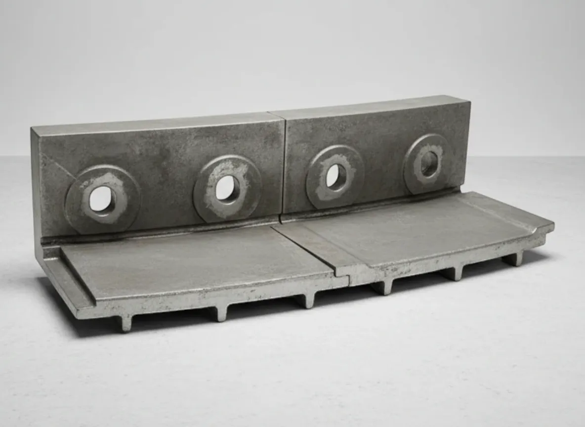
Shell Sections & Tyre Pads
Replacement kiln shell sections for damaged, thinned or corroded areas — rolled and welded to kiln specifications with proper material transitions and weld procedure qualifications. Tyre pads (chairs) are the support elements between the kiln shell and the riding ring, accommodating thermal expansion while maintaining tyre position and load transfer. Both require precise dimensional control for installation.
Material Specifications for Kiln Components
Kiln component materials split into two categories: structural steels (cast or forged) for load-bearing components (tyres, rollers) that operate at 250–350°C, and heat-resistant alloys for the kiln hot zone (nose rings, hood liners) exposed to 1,000–1,100°C. Selecting the correct grade for each application ensures both mechanical performance and economic service life.
Cast Steel (G20Mn5)
EN 10293 G20Mn5 cast steel (160–200 HB)
Standard-duty kiln tyres — good machinability, adequate mechanical strength and fatigue life for kilns with moderate loading per support station
20–30 years (standard duty)
Limitation: Lower fatigue strength than forged 42CrMo4 — may not achieve 30-year target life on heavily loaded, high-speed or large-diameter kilns
Forged Steel (42CrMo4)
EN 10083 42CrMo4 forged alloy steel (250–300 HB)
Heavy-duty tyres, support rollers and thrust rollers — superior fatigue strength, higher hardness and better load-bearing capacity for high-load applications
25–30+ years (heavy duty)
Limitation: Higher material and machining cost than cast steel. Forging process limits maximum cross-section — very large tyres may require cast alternatives
Induction Hardened Steel
42CrMo4 base with 50–55 HRC induction-hardened surface (2–5 mm case depth)
Support roller running surfaces where maximum surface wear resistance is combined with tough core to resist subsurface fatigue — the standard for high-speed and high-load kilns
Running surface: 15–25 years before re-grinding
Limitation: Induction hardening requires careful control of case depth and transition zone — incorrect process can create subsurface stress concentrations that initiate spalling
HK40 / HP40 (Heat-Resistant Alloys)
ASTM A297 HK40 (25Cr-20Ni) / HP40 (25Cr-35Ni)
Nose ring castings and kiln hood liners exposed to temperatures of 1,000–1,100°C continuous — provides oxidation resistance, creep strength and thermal fatigue life at the kiln discharge end
5–10 years for nose rings (position-dependent)
Limitation: Brittle compared to structural steels — not suitable for load-bearing applications. Service limited to the kiln hot zone where heat resistance is the primary requirement
Kiln Component Material Selection Framework
Standard-duty kiln tyres? → Cast steel G20Mn5 — proven, cost-effective for moderate loading per support station
Heavy-duty tyres, support and thrust rollers? → Forged 42CrMo4 — superior fatigue strength for high-load, large-diameter kilns
Support roller running surfaces (high-speed kilns)? → 42CrMo4 with induction hardening to 50–55 HRC for maximum surface wear resistance
Nose rings and kiln hood liners (1,000–1,100°C)? → HK40 or HP40 heat-resistant alloys per ASTM A297
All steel components supplied with material test certificates per EN 10204 Type 3.1 or equivalent. Contact ATF with your kiln specifications and loading data for component-specific material recommendations.
Compatible Kiln Brands & Models
ATF manufactures replacement kiln tyres, support rollers, thrust rollers, nose ring castings and structural components for all major cement kiln suppliers. Our engineering team can work from OEM drawings or reverse-engineer parts from samples, measurements and site survey data.
FLSmidth
ROTAX-2 Kilns, Unax Kilns, Cross-Bar Cooler kiln lines
Including legacy Fuller and F.L.Smidth designs
thyssenkrupp (Polysius)
POLRO Kilns, Two-Support Kilns, Three-Support Kilns
ThyssenKrupp Industrial Solutions — Polysius kiln technology
KHD Humboldt Wedag
PYRORAPID Kilns, Roller Kiln Systems
Including legacy Humboldt Wedag kiln designs
CBMI / Sinoma
5,000 t/d and 10,000 t/d kiln lines, complete pyroprocessing systems
CBMI Construction — Sinoma International cement technology
Fives (FCB)
Pilard Kilns, Flash Calciner kiln lines
Fives Group / FCB cement kiln systems
Others
Outotec (pelletizing/calcining kilns), IKN, Claudius Peters, Chinese-manufactured kilns
Contact ATF with kiln nameplate data for component fit confirmation
Don’t see your kiln manufacturer? ATF can reverse-engineer kiln components from site measurements and existing part samples for any rotary kiln. Send your kiln nameplate data, drawings or component dimensions for fit confirmation.
Verify Your KilnNeed Kiln Components for Your Cement Plant?
Send your kiln specifications, current component condition and shutdown schedule. ATF will provide engineered replacement parts with complete material certification and quality documentation.
Rotary Kiln Component Maintenance Best Practices
Kiln mechanical components operate under continuous fatigue loading, thermal stress and environmental exposure. Systematic inspection and condition monitoring extends service life, prevents unplanned shutdowns and maintains the kiln alignment that protects both the refractory lining and the shell from premature damage.
Every Shift
- Monitor tyre and support roller surface temperatures using IR scanning — hot spots indicate misalignment or lubrication failure
- Check support roller bearing temperatures and lubrication oil flow — overheating indicates bearing or alignment issues
- Monitor kiln axial position (migration) — excessive drift indicates thrust roller wear or hydraulic system failure
- Listen for abnormal sounds at support stations — metallic grinding or thumping suggests roller/tyre surface damage
Weekly
- Inspect tyre-to-shell creep gap (for floating tyre designs) — measure at multiple circumferential positions
- Check tyre retaining block (stop block) condition and bolt torque — loose blocks allow tyre lateral migration
- Monitor kiln shell ovality at each tyre station using proximity probes or manual measurements
- Inspect thrust roller contact pattern and bearing condition — check for signs of overloading or misalignment
Monthly
- Measure support roller and tyre running surface wear using portable profilometers or template gauges
- Check kiln alignment by plotting tyre centre-line positions against reference datum — monitor for support station settlement
- Inspect nose ring segment condition through kiln hood access — check for cracking, erosion or clinker buildup
- Review tyre pad condition (for welded tyre designs) — look for cracking at pad-to-shell weld connections
Annual Shutdown
- Complete tyre and support roller profile measurement — full surface mapping to assess wear pattern and remaining life
- Inspect tyre bore and kiln shell contact surfaces under the tyre for fretting, corrosion or heat discoloration
- Replace nose ring segments worn beyond minimum thickness or showing thermal fatigue cracking
- Inspect and re-grind support roller running surfaces if wear exceeds profile tolerance (in-situ grinding)
- Check all tyre pad welds, retaining blocks and foundation bolts — tighten or replace as required
- Measure kiln shell thickness at high-wear zones using ultrasonic gauges — map the corrosion/erosion pattern
Typical Kiln Component Specifications by Kiln Size
| Parameter | Small (3.0–4.0 m) | Medium (4.0–5.0 m) | Large (5.0–6.2 m) |
|---|---|---|---|
| Capacity | 1,000–2,500 t/d | 2,500–5,000 t/d | 5,000–12,000 t/d |
| Tyre Weight | 15–40 tonnes | 40–80 tonnes | 80–150 tonnes |
| Tyre Material | Cast G20Mn5 | Cast or Forged | Forged 42CrMo4 |
| Support Stations | 2-pier | 2 or 3-pier | 3-pier |
| Roller Hardening | Optional | Recommended | Required (50–55 HRC) |
| Nose Ring Alloy | HK40 | HK40 / HP40 | HP40 |
Specifications are indicative. Actual requirements depend on kiln dimensions, support configuration, rotational speed, inclination and production rate. Contact ATF with your kiln data for component-specific recommendations.
Common Rotary Kiln Problems & Solutions
Kiln mechanical component issues have cascading effects on refractory life, shell integrity and production output. Early identification and corrective action prevents expensive unplanned shutdowns and extends the life of both mechanical and refractory components.
Tyre or Roller Surface Damage (Pitting, Spalling)
Probable Causes
- Contact stress exceeding material fatigue limit — overloaded support station from misalignment or foundation settlement
- Incorrect roller crown profile creating edge loading instead of distributed contact across the full width
- Lubrication failure on floating tyre designs — metal-to-metal contact at the tyre-to-shell interface generates heat and surface damage
- Foreign material (clinker, debris) trapped between tyre and roller running surfaces
Corrective Actions
- Check kiln alignment and support station loading — re-shim or adjust to restore correct load distribution
- Measure roller and tyre profiles — re-grind in-situ if profiles have worn beyond contact tolerance
- Inspect and restore lubrication system for floating tyres — verify oil delivery rate and tyre bore condition
- Install or improve guarding to prevent material ingress at tyre/roller contact zones
Excessive Kiln Shell Ovality
Probable Causes
- Tyre-to-shell creep gap too large (floating tyre) — tyre not supporting the shell across sufficient arc
- Refractory lining failure creating a hot spot that weakens the shell locally
- Support station misalignment causing non-uniform support — one station carrying disproportionate load
- Worn tyre pads (welded tyre) allowing uneven load transfer from shell to tyre
Corrective Actions
- Measure creep gap at all tyre stations — restore to OEM specification by shimming or tyre replacement if excessively worn
- Inspect refractory lining at hot spot location — repair or replace to restore uniform thermal protection
- Check kiln alignment across all support stations — adjust to correct load distribution
- Inspect tyre pads and shell-to-pad welds — replace cracked or worn pads to restore load transfer
Excessive Kiln Migration (Axial Movement)
Probable Causes
- Thrust roller wear reducing the effective restraint — worn contact surfaces allow axial drift
- Thrust roller hydraulic system failure — insufficient pressure to maintain kiln position
- Support roller skew angle incorrect — rollers driving the kiln uphill or downhill instead of maintaining neutral position
- Thermal expansion changes from process variations — kiln lengthening or shortening with temperature changes
Corrective Actions
- Inspect thrust roller contact surface and bearing condition — replace if worn beyond effective restraint
- Check hydraulic system pressure, accumulator charge and cylinder seals — repair any leaks or failures
- Verify support roller skew angles — adjust to achieve neutral kiln position at normal operating temperature
- Review process stability — consistent kiln operation reduces thermal expansion variation
Nose Ring Cracking or Segment Loss
Probable Causes
- Thermal fatigue from cycling between 1,000–1,100°C during operation and ambient during shutdowns
- Clinker buildup between segments creating mechanical stress that forces segments apart
- Incorrect alloy grade — using HK40 where HP40 is needed for higher-temperature exposure
- Mechanical impact from large clinker lumps or coating collapse in the burning zone
Corrective Actions
- Implement controlled kiln cooling during shutdown (≤50°C/hour) to reduce thermal shock to nose ring castings
- Clean clinker buildup from between segments during each shutdown — restore designed expansion gaps
- Review alloy selection — upgrade to HP40 for segments at the highest temperature exposure positions
- Replace damaged segments individually (segmented designs allow 2–3 day changeout vs 7–14 days for complete ring)
Support Roller Bearing Failure
Probable Causes
- Overloading from kiln misalignment — one bearing carrying more than its design share of the kiln mass
- Lubrication failure — oil degradation, contamination or insufficient flow to bearings
- Foundation settlement changing the support geometry and creating angular misalignment at the bearing
Corrective Actions
- Check kiln alignment and per-station loading — redistribute load across all support stations evenly
- Review lubrication system — change oil, flush system, check flow rates and install contamination monitoring
- Survey foundations and re-level support stations if settlement is detected — grout and re-shim as required
Frequently Asked Questions
Answers to common questions about rotary kiln tyres, support rollers, nose rings, material selection and ordering. Can’t find what you’re looking for?
Contact Our TeamWhat is the typical service life of kiln tyres?
How do you ensure support roller compatibility with existing tyres?
Can nose ring segments be replaced individually?
What is the difference between cast and forged kiln tyres?
What information does ATF need to quote kiln components?
Are ATF kiln components compatible with OEM equipment?
What NDT and quality documentation is provided?
What is the typical lead time for kiln components?
Keep Your Kiln Running
Precision-engineered kiln components that support continuous cement production. ATF provides full material certification, NDT documentation and delivery timing coordinated to your shutdown schedule.
Contact ATF EngineeringRequest a Free Quote Today
Our engineering team responds within 24 hours with detailed specifications, material recommendations, and competitive pricing.