

Slurry Pump Parts
Slurry Pump Parts | Impellers Volutes Cr27 | ATF
Wet-end pump parts: impellers volutes throatbush frame liners. Cr27 high-chrome rubber ceramic options. Send pump model for exact fit.
Aftermarket Slurry Pump Parts for Mining & Mineral Processing
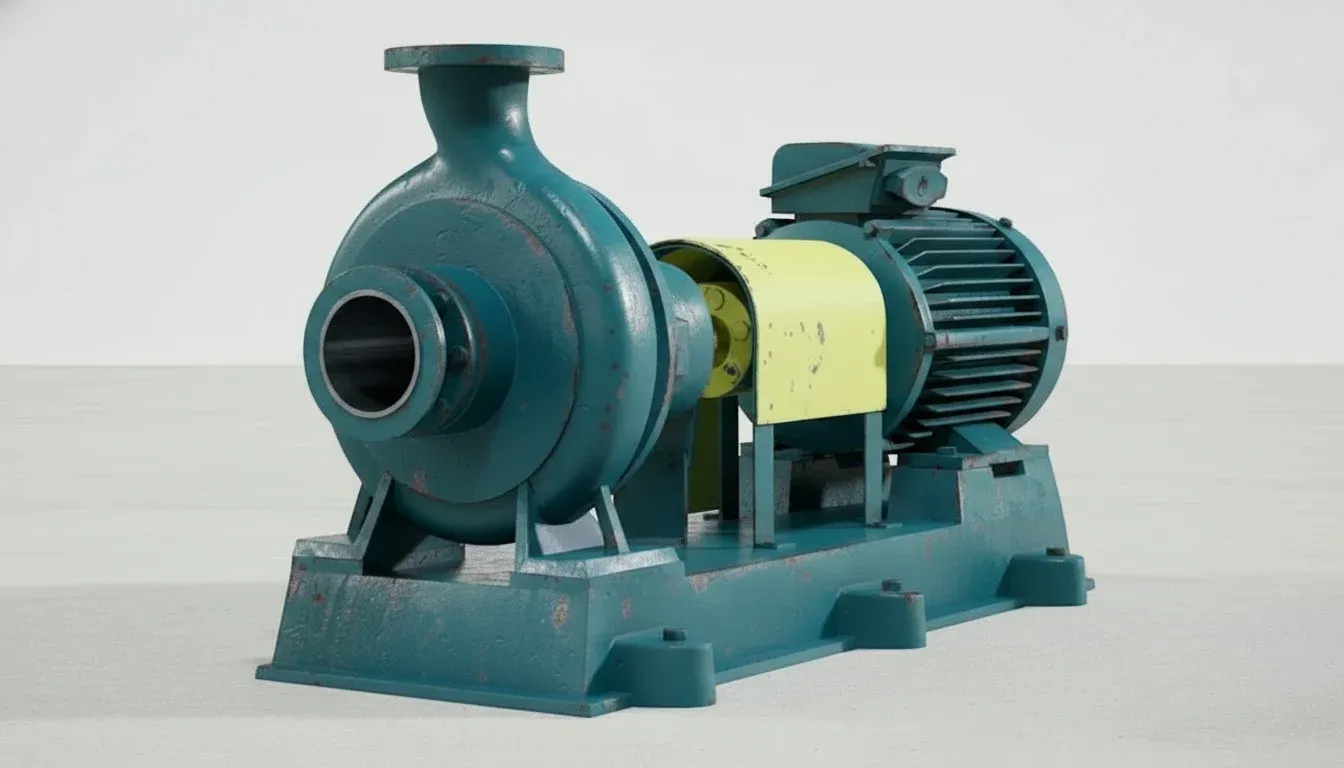
Centrifugal slurry pumps are the workhorses of mining and mineral processing — moving millions of tonnes of abrasive slurry through mill discharge, cyclone feed, flotation, tailings and concentrate circuits. Wet-end components — impellers, volute liners, throatbush liners and frame plates — face continuous erosion-corrosion from slurries containing 10–50% abrasive solids by weight, including silica, alumina, magnetite and other hard minerals at velocities of 10–25 m/s.
ATF manufactures aftermarket wet-end components in high-chrome white iron (A05 Cr27 at 600–650 BHN, A07 Cr27Mo at 650–700 BHN, A49 hyperchrome at 700+ BHN), natural rubber (R55 at 55 Shore A, R26 at 40 Shore A), neoprene and polyurethane — matching OEM specifications for Warman/Weir, Metso, KSB GIW, ITT Goulds, Flowserve and other major pump brands. All hydraulic profiles are 3D-scanned and CMM-verified to ensure replacement parts maintain original pump curve characteristics and efficiency.
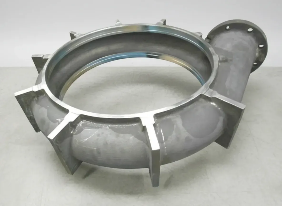
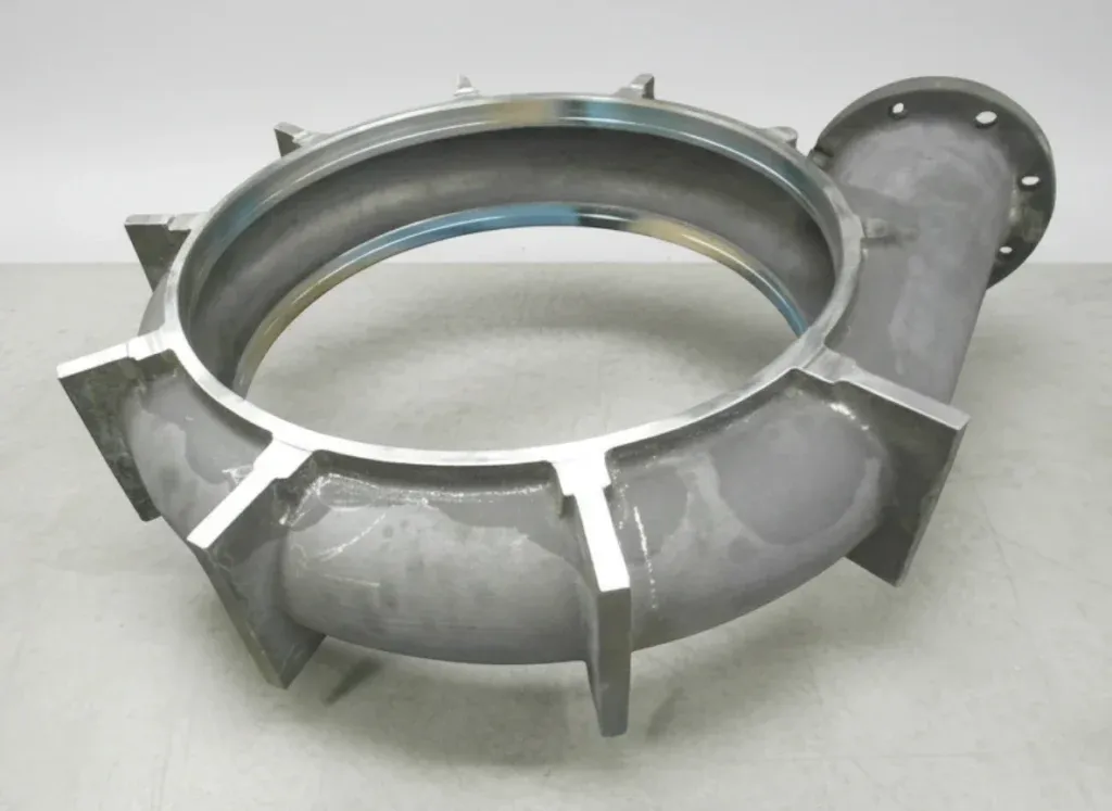
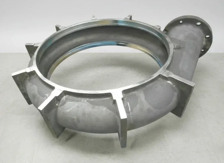
ATF slurry pump wet-end components — impellers, volute liners, throatbush liners and frame plates in high-chrome white iron and rubber for mining and mineral processing applications.
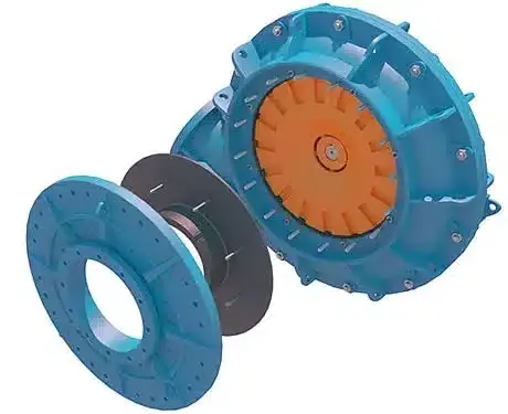
How Centrifugal Slurry Pumps Work
Understanding how slurry moves through the pump — and where wear occurs at each stage — explains why material selection differs between components and why operating the pump near its Best Efficiency Point (BEP) is critical to maximising wet-end component life.
Suction & Intake
Slurry enters the pump through the suction pipe and passes through the throatbush into the impeller suction eye. The throatbush forms a critical clearance with the rotating impeller — typically 1.5–3 mm — that controls internal recirculation. As this clearance wears open, high-pressure slurry recirculates from the discharge side back to the suction, reducing net flow and accelerating erosion at the clearance gap. This is why throatbush condition is the single most important factor in maintaining pump efficiency.
Impeller Energy Transfer
The rotating impeller vanes accelerate slurry outward through centrifugal force at tip speeds of 15–30 m/s, converting mechanical shaft energy into hydraulic energy (pressure and velocity). Each vane leading edge, tip and shroud surface is subjected to continuous erosive attack from abrasive particles in the slurry. Wear creates an enlarged suction eye, thinner vanes and eroded shrouds — all reducing the impeller's ability to transfer energy efficiently. Impellers are dynamically balanced to ISO 1940 G2.5 to minimise vibration.
Volute Collection & Discharge
High-velocity slurry exits the impeller periphery and enters the volute — a spiral-shaped passage that progressively expands to convert kinetic energy into static pressure. The cutwater (tongue) region where the volute begins experiences concentrated erosion from slurry impact at high angles. The volute liner protects the structural steel casing from this erosion. Frame plate liners on the drive side and expeller rings provide shaft sealing by generating back-pressure that prevents slurry from reaching the mechanical seal or packing.
Slurry Pump Wet-End Components
ATF manufactures the complete range of wet-end wear components for centrifugal slurry pumps — from the impeller at the centre to the volute liner, throatbush, frame plate and expeller. Each component operates under different erosion conditions and may benefit from a different material.
Impellers
The rotating heart of the pump — vanes accelerate slurry outward through centrifugal force, converting mechanical energy into hydraulic energy. Impeller condition is the single most significant factor determining pump head, flow, efficiency and maintenance intervals. Available in high-chrome white iron (A05, A07, A49), natural rubber (R55, R26), neoprene and polyurethane.
Volute Liners & Casings
The spiral-shaped casing liner that collects high-velocity slurry from the impeller periphery and converts kinetic energy into static pressure. Volute geometry — cutwater angle, throat area, discharge dimensions — directly affects pump efficiency and radial thrust. Single-piece and split (two-piece) designs available for all pump frame sizes.
Throatbush Liners
Suction-side wear component that forms the transition between the pump casing and the impeller suction eye. The throatbush controls the clearance between the rotating impeller and stationary casing — a critical dimension that directly affects pump efficiency, internal recirculation and wear rate. Worn throatbush clearance is the primary cause of efficiency loss in slurry pumps.
Frame Plates, Expellers & Other Parts
Back liner plates (frame plate liners), expeller rings, shaft sleeves, stuffing box components and mechanical seal interfaces. Frame plate liners protect the drive-side casing from erosion. Expellers provide dynamic sealing by generating back-pressure that prevents slurry from reaching the shaft seal — reducing seal wear and maintenance cost.
Slurry Pump Material Selection
Material selection for slurry pump wet-end components is driven by particle size distribution (D85 above or below 150 microns is the primary threshold), slurry pH, temperature, and solids concentration. The optimal material often differs between pump positions — impeller, volute, throatbush — because each sees different erosion conditions.
A05 High-Chrome (Cr27)
ASTM A532 Class III Type A — 27% Cr, 2.5–3.0% C
Mill discharge, cyclone feed and coarse tailings pumping — the industry standard for mining slurry pumps handling particles >150 microns at neutral to alkaline pH
2,000–6,000 hours (application-dependent)
Limitation: Susceptible to corrosion-accelerated erosion in acidic slurries (pH <5). Not recommended for fine-particle applications where rubber outperforms chrome 1.5–3x
A07 High-Chrome (Cr27Mo)
ASTM A532 Class III — 27% Cr, 1.5% Mo, 2.5–3.0% C
Highly abrasive slurries with moderate corrosion — molybdenum addition improves corrosion resistance in mildly acidic conditions (pH 4–6) while maintaining high hardness
2,500–7,000 hours (corrosive-abrasive service)
Limitation: Higher cost than A05 — use only where corrosion-erosion synergy is documented, otherwise A05 provides equivalent erosion resistance at lower cost
A49 Hyperchrome
Proprietary hypereutectic chrome iron — 30%+ Cr, high C
Ultra-abrasive applications — mineral sands, heavy media circuits, fine magnetite processing — where maximum hardness is needed for extreme erosion resistance
3,000–8,000 hours (ultra-abrasive service)
Limitation: Low impact toughness — brittle under sudden impact or thermal shock. Not suitable for pumps handling large oversize particles or experiencing frequent starts/stops
R55 Natural Rubber (55 Shore A)
Natural rubber compound — 55 Shore A hardness, 500%+ elongation
Fine particle slurries (<150 microns D85), flotation circuit, tailings transfer and corrosive slurries (pH 2–12) — rubber's resilient surface deflects fine particles rather than allowing them to cut
3,000–8,000 hours (fine particle service)
Limitation: Temperature limited to ~70°C. Degrades in hydrocarbon-contaminated slurries. Not suitable for coarse particles >150 microns which cut through rubber rapidly
R08 Neoprene (Chloroprene)
Polychloroprene rubber — 65 Shore A, moderate oil resistance
Slurries contaminated with oils, greases or solvents where natural rubber would swell and degrade — common in mineral processing circuits with flotation reagent carryover
2,000–5,000 hours (chemical service)
Limitation: Inferior erosion resistance compared to natural rubber in clean slurries — use only where oil/chemical resistance is specifically required
Material Selection Decision Framework
D85 > 150 microns (coarse)? → High-chrome A05 or A07 — hard carbide matrix resists gouging from coarse particles
D85 < 150 microns (fine)? → Natural rubber R55 — resilient surface deflects fine particles, 1.5–3x chrome life
Acidic pH (<5)? → Rubber strongly preferred — chrome suffers corrosion-accelerated erosion in acid
Temperature >70°C? → Chrome required — rubber degrades above 70°C
Ultra-abrasive (mineral sands)? → A49 hyperchrome (700+ BHN) for maximum erosion resistance
Send ATF your slurry data — particle size distribution, pH, temperature, solids concentration and pump duty point — for position-specific material recommendations optimised for minimum total cost of ownership.
Compatible Pump Brands & Models
ATF manufactures aftermarket wet-end components for all major slurry pump brands used in mining and mineral processing worldwide. All parts are dimensionally verified against OEM specifications with guaranteed fit and hydraulic performance.
Warman / Weir Minerals
AH Series (1.5/1 through 20/18), AHP High Pressure, L Light Duty, M Medium Duty, HH Heavy Duty High Head
Complete wet-end replacement parts for all Warman frame sizes
Metso (Sala/Thomas/Orion)
HM Series, HR Series, HS Series, MD Mill Discharge, VF Froth Pumps
Aftermarket parts matching Metso dimensional and hydraulic specifications
KSB GIW
LSA Series, LCC Series, LCV Series, MDX Mill Duty, TBC Tailings/Booster
GIW Industries replacement parts for mining and dredging applications
ITT Goulds
XHD Extra Heavy Duty, SRL Slurry, 5500 Series, CV 3196 Chemical/Slurry
Goulds Pumps slurry and process pump replacement components
Flowserve
Durco Mark III Slurry, IDP Slurry Pumps
Flowserve process and slurry pump replacement parts
Others
Schurco Slurry (S/H/SC Series), Habermann, Krebs, Galigher, Chinese-manufactured pumps
Contact ATF with pump model and part numbers for compatibility confirmation
Don't see your pump model? ATF manufactures aftermarket parts from OEM drawings or reverse-engineered from samples for any centrifugal slurry pump. Send your pump model and part numbers for fit confirmation and material recommendation.
Verify Your PumpNeed Slurry Pump Parts?
Send your pump model, current operating conditions and slurry data. ATF will recommend the optimal material for each wet-end position and provide competitive pricing with delivery timing matched to your maintenance schedule.
Slurry Pump Maintenance Best Practices
Slurry pump wet-end wear directly affects pump efficiency, flow delivery and energy consumption. Systematic performance monitoring and clearance management extends component life and enables planned replacement rather than emergency shutdowns.
Every Shift
- Monitor pump discharge pressure and flow rate — declining head at constant speed indicates impeller or liner wear
- Check pump bearing temperature and vibration — rising values indicate imbalance from uneven impeller wear or bearing deterioration
- Monitor motor current draw — increasing power at constant flow suggests worn impeller or internal recirculation from clearance issues
- Check gland water flow and shaft seal condition — slurry leakage past the seal indicates worn packing, sleeve or expeller
Weekly
- Measure and record pump discharge pressure, flow and power — track performance trends against the pump curve
- Adjust impeller-to-throatbush clearance if adjustable — maintain OEM specification (typically 1.5–3 mm depending on pump size)
- Check expeller back-pressure by observing gland condition — insufficient expeller performance means slurry reaches the shaft seal
- Inspect suction and discharge piping connections for wear, leaks or restriction that affects pump operating point
Monthly
- Plot pump performance against the original pump curve — determine efficiency loss from wear and plan replacement timing
- Inspect accessible wet-end components through inspection covers — check for localised erosion patterns indicating flow issues
- Check shaft run-out at the packing location — excessive run-out indicates shaft sleeve wear or bearing deterioration
- Review vibration trend data — increasing vibration at 1x RPM indicates rotor imbalance from impeller wear
Planned Shutdown
- Complete wet-end inspection — measure impeller vane thickness, throatbush bore diameter, volute throat area and frame plate liner thickness
- Replace impeller if efficiency loss exceeds 10–15% or if vane thickness is below minimum — install as dynamically balanced assembly
- Replace throatbush if bore diameter exceeds maximum clearance specification — worn clearance is the primary cause of efficiency loss
- Replace volute liner if throat area has enlarged significantly or if localised erosion has created leak paths
- Inspect and replace shaft sleeve, packing/seal components and expeller as needed
- Document all wear measurements and calculate wear rates — optimise material selection and replacement intervals based on actual data
Slurry Pump Wear Indicators
| Indicator | Normal Range | Action Threshold | Likely Component |
|---|---|---|---|
| Head decline | 0–5% | 10–15% loss | Impeller vane wear |
| Flow decline | 0–5% | 10–15% loss | Throatbush clearance |
| Power increase | 0–5% | >10% rise | Internal recirculation |
| Vibration (1x RPM) | <4 mm/s | >7 mm/s | Impeller imbalance |
| Bearing temperature | <80°C | >95°C | Bearing / seal issue |
Thresholds are general guidelines — establish site-specific baselines for each pump based on new-condition performance data. Trend monitoring is more valuable than absolute values.
Common Slurry Pump Problems & Solutions
Slurry pump performance issues affect process throughput, energy consumption and maintenance costs. Identifying the root cause — whether hydraulic, mechanical or material-related — enables targeted corrective action rather than wholesale wet-end replacement.
Declining Pump Head or Flow Rate
Probable Causes
- Impeller vane erosion — reduced vane area decreases energy transfer to the slurry, lowering head and flow
- Worn throatbush clearance — enlarged gap allows internal recirculation from discharge back to suction, reducing net flow
- Volute throat erosion — enlarged throat area changes the velocity-to-pressure conversion, shifting the pump curve
- Worn suction liner or frame plate allowing internal bypass flow paths
Corrective Actions
- Measure impeller vane thickness — compare to new dimensions and replace if below minimum threshold
- Check and adjust impeller-to-throatbush clearance — if beyond maximum adjustment, replace the throatbush
- Measure volute throat area — replace liner if throat has enlarged more than 10–15% from original
- Inspect all wet-end sealing faces — replace components with worn or damaged mating surfaces
Excessive Vibration
Probable Causes
- Impeller imbalance from uneven wear — one side of the impeller erodes faster, creating mass imbalance
- Damaged or missing impeller vane section — a broken vane creates severe rotor imbalance
- Bearing wear or damage from inadequate lubrication, contamination or overloading
- Cavitation — vapour bubble formation and collapse at the impeller inlet creating irregular loading
Corrective Actions
- Inspect impeller for uneven wear or missing sections — replace if imbalance cannot be corrected
- Check bearing condition — measure clearances and replace if beyond specification
- Verify NPSH available exceeds NPSH required by minimum 1.5x margin — increase suction head or reduce flow if cavitating
- Check for air entrainment in the suction — verify sump level, suction pipe submergence and pipe joints
Rapid Impeller or Liner Wear
Probable Causes
- Operating far from Best Efficiency Point (BEP) — flows below 80% or above 110% of BEP create recirculation and separation that accelerate wear
- Incorrect material for the slurry — using chrome in fine-particle service where rubber would last 2–3x longer (or vice versa)
- Excessive solids concentration exceeding pump design limits — higher than specified Cw or Cv values
- Cavitation-erosion from insufficient NPSH margin — vapour bubble collapse creates severe pitting on suction shroud and vane leading edges
Corrective Actions
- Review pump operating point against the curve — adjust system resistance or pump speed to operate within 80–110% of BEP
- Re-evaluate material selection based on particle size distribution — D85 above 150 microns favours chrome, below favours rubber
- Check actual slurry density and solids concentration against pump design parameters
- Increase NPSH available — raise sump level, shorten/enlarge suction pipe, or reduce pump speed
Shaft Seal Leakage or Failure
Probable Causes
- Worn shaft sleeve — slurry erosion of the sleeve surface creates leak paths past packing rings or mechanical seal faces
- Expeller wear — reduced back-pressure allows slurry to reach the packing/seal area where it accelerates seal wear
- Incorrect gland water pressure — too low allows slurry ingress, too high wastes water and can hydraulically overload the seal
- Shaft deflection from impeller imbalance or bearing wear — misalignment causes uneven seal loading and premature failure
Corrective Actions
- Inspect and replace shaft sleeve if worn below minimum diameter — consider ceramic or tungsten carbide coated sleeves for extended life
- Check expeller condition and clearance — replace if worn to the point where slurry bypasses to the seal area
- Adjust gland water pressure to 35–70 kPa above pump suction pressure — clean water should weep from the gland
- Check bearing condition and shaft run-out — correct any imbalance or alignment issues before replacing seal components
Pump Cavitation (Noise, Pitting, Performance Loss)
Probable Causes
- Insufficient NPSH available — sump level too low, suction pipe too long/small, or suction-side restriction
- Slurry temperature too high — elevated temperature reduces vapour pressure margin, promoting cavitation
- Air entrainment from vortexing in the sump, leaking suction pipe joints, or insufficient pipe submergence
- Operating at excessive flow rate — NPSH required increases with flow, and at high flows may exceed NPSH available
Corrective Actions
- Increase NPSH available: raise sump level, shorten/enlarge suction pipe, remove restrictions, reduce pipe friction losses
- Reduce pump speed — NPSHR decreases with speed cubed, providing significant cavitation margin improvement
- Install anti-vortex baffles in the sump and ensure suction pipe submergence is at least 2x pipe diameter
- Reduce flow rate to bring operating point back within the pump's cavitation-free range on the performance curve
Frequently Asked Questions
Answers to common questions about slurry pump materials, impeller selection, maintenance, troubleshooting and ordering. Can't find what you're looking for?
Contact Our TeamShould I use rubber or chrome wet-end components?
Can I mix materials between impeller and liners?
How do I know when to replace slurry pump impellers?
What information do you need to quote slurry pump parts?
What causes premature impeller wear?
Are ATF parts guaranteed to fit OEM pumps?
What is the advantage of A49 hyperchrome over standard A05?
What is the typical lead time for slurry pump parts?
Optimize Your Slurry Pump Performance
Aftermarket wet-end components engineered for mining and mineral processing. ATF provides application-specific material recommendations, OEM-fit guarantee and competitive pricing for all major pump brands.
Contact ATF EngineeringRequest a Free Quote Today
Our engineering team responds within 24 hours with detailed specifications, material recommendations, and competitive pricing.