

Peças para Moinho SAG
Revestimentos para Moinho SAG | Carcaça, Extremidade e Grelhas | ATF
Peças para moinhos SAG: revestimentos, barras elevadoras e grelhas em cromo-molibdênio, aço liga e borracha-aço. Envie tamanho do moinho e dados do minério.
Soluções completas de revestimentos para moinhos SAG
Os moinhos SAG (Semi-Autogenous Grinding) utilizam o próprio minério como meio de moagem, complementado com uma pequena carga de bolas de aço (8–15%). A combinação resultante de moagem autógena por impacto e atrito assistido por bolas faz dos moinhos SAG o cavalo de batalha dos circuitos modernos de cominuição — processando minério ROM de 300 mm de alimentação até produto de 10–25 mm em uma única etapa. Os moinhos SAG são o maior equipamento rotativo de moagem na mineração, com diâmetros de até 12,2 m (40 ft) e potências de acionamento superiores a 25 MW.
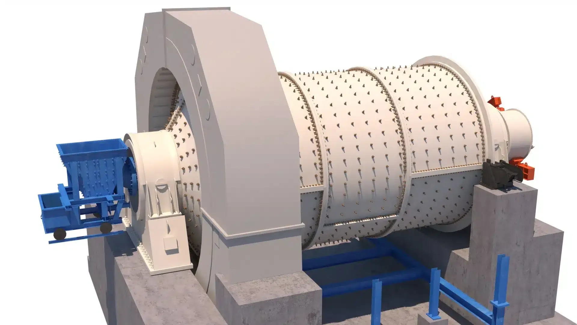
Cada componente de desgaste em um moinho SAG opera em condições extremas: os revestimentos da carcaça absorvem o impacto de blocos de minério em catarata de mais de 5 m de altura, as barras elevadoras controlam uma carga combinada que pesa centenas de toneladas, e os painéis de grelha precisam equilibrar a descarga de polpa com a extração de seixos. A ATF projeta e fabrica a linha completa de revestimentos, barras elevadoras, painéis de grelha e componentes de descarga para moinhos SAG conforme especificações OEM — com classes de liga, geometrias de perfil e configurações de portas de seixos otimizadas para o seu minério e circuito de moagem específicos.

Revestimentos ATF para moinhos SAG — revestimentos da carcaça, barras elevadoras de alto perfil e painéis de grelha com portas de seixos em aço cromo-molibdênio e configurações bimetálicas, projetados para moagem semi-autógena de alto impacto.
Mecanismo de moagem semi-autógena
Compreender como o impacto minério contra minério, o atrito assistido por bolas e o controle da trajetória da carga atuam em conjunto explica por que o perfil do revestimento, a geometria da barra elevadora e o projeto da grelha determinam diretamente a eficiência de moagem, o consumo de energia, a capacidade e o custo por tonelada moída.
Alimentação e elevação da carga
O minério ROM (run-of-mine) (até 300 mm) entra no moinho SAG pelo munhão de alimentação junto com os seixos recirculados. À medida que o moinho gira a 70–78% da velocidade crítica, as barras elevadoras de alto perfil (200–350 mm) carregam a carga combinada de minério e bolas de aço para cima ao longo da parede da carcaça. A altura e o ângulo de face do elevador determinam o ângulo do ombro — até que altura a carga é elevada antes de se desprender do revestimento e iniciar sua descida em direção à zona do pé.
Moagem por impacto e atrito
O minério é reduzido por dois mecanismos: impacto por catarata (grandes blocos de minério e bolas de aço caem livremente pelo ar e se chocam contra a carga — fraturando partículas grosseiras) e atrito por cascata (o minério rola pela superfície da carga — moendo por abrasão e compressão entre partículas). O equilíbrio entre esses mecanismos é controlado pela velocidade do moinho, pelo perfil do elevador, pelo nível da carga de bolas e pela competência do minério. Essa dupla ação de moagem permite que os moinhos SAG processem minério ROM em uma única etapa.
Descarga e extração de seixos
A polpa moída passa pelas aberturas dos painéis de grelha (10–40 mm), enquanto os seixos de tamanho crítico (50–100 mm) são extraídos por portas dedicadas (80–120 mm) e enviados a um britador de seixos para nova redução antes de retornarem à alimentação do moinho. Os canais elevadores de polpa transportam a polpa da face da grelha até o munhão de descarga. Uma peneira trommel na descarga classifica o produto antes que ele passe para a próxima etapa — tipicamente um moinho de bolas ou circuito de classificação.
Revestimentos e componentes de desgaste para moinhos SAG
Um moinho SAG requer cinco categorias de componentes de desgaste e estruturais. Cada página de componente fornece opções detalhadas de materiais, orientações de projeto de perfil e informações de compatibilidade OEM para o seu moinho específico.
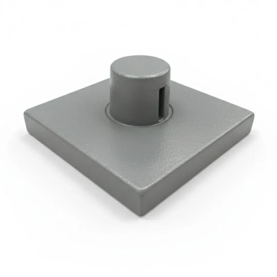
Revestimentos da carcaça
Protegem a carcaça cilíndrica contra o impacto direto de grandes blocos de minério e dos corpos moedores de aço. Os revestimentos da carcaça dos moinhos SAG precisam suportar energias de impacto muito maiores do que os revestimentos de moinhos de bolas — pedaços de minério de até 300 mm impactam o revestimento em alta velocidade durante a catarata. Os designs de perfil de alta elevação e ondulado controlam a trajetória da carga e a ação de moagem.
Revestimentos de extremidade
Protegem os tampos do lado de alimentação e do lado de descarga do moinho SAG. Os revestimentos do lado de alimentação incorporam a geometria da abertura de alimentação e devem suportar o impacto direto do minério grosseiro entrante. Os revestimentos do lado de descarga se integram ao arranjo dos painéis de grelha e precisam manter a geometria correta para o suporte da grelha e o alinhamento dos elevadores de polpa.
Barras elevadoras
Elementos elevados de alto perfil que erguem a carga combinada de minério e bolas de aço. As barras elevadoras dos moinhos SAG são significativamente mais altas do que as de moinhos de bolas (200–350 mm) para suportar a carga maior e mais pesada. A altura da barra elevadora, o ângulo de face e o espaçamento entre fileiras controlam o equilíbrio entre moagem por impacto (catarata) e moagem por atrito (cascata) — determinando diretamente a capacidade e a eficiência energética.
Painéis de grelha
Painéis perfurados de descarga que retêm os corpos moedores e o minério sobredimensionado enquanto deixam passar a polpa moída. As grelhas dos moinhos SAG apresentam tanto aberturas finas (10–40 mm) para a descarga do produto quanto portas de seixos (80–120 mm) para extrair os seixos de tamanho crítico, que recirculam para um britador de seixos. A área aberta da grelha (8–25%) controla diretamente a capacidade de produção do moinho.
Peças de reposição adicionais
Revestimentos do munhão, canais elevadores de polpa, calhas de alimentação, peneiras trommel e parafusaria do moinho. Esses componentes estruturais e de controle de fluxo mantêm a geometria do moinho, protegem elementos estruturais de alto valor e gerenciam a descarga do material. Os revestimentos do munhão, em particular, protegem os caros e não substituíveis munhões do moinho contra o desgaste abrasivo da polpa.
Seleção de materiais para revestimentos de moinho SAG
A seleção de liga para revestimentos de moinho SAG é dominada pela tenacidade ao impacto — a energia dos blocos de minério e das bolas de aço em catarata em um moinho de 6–12 m de diâmetro é muito superior à de um moinho de bolas. O aço cromo-molibdênio é o padrão porque absorve essa energia sem trincar. As ligas bimetálicas e de alto cromo são usadas seletivamente em posições de menor impacto para prolongar a vida útil.
Aço cromo-molibdênio
Cr-Mo alloy steel (325–450 BHN)
O padrão da indústria para revestimentos da carcaça e barras elevadoras de moinhos SAG — tenacidade comprovada para suportar o impacto de alta energia de minério grande e bolas de aço de 125 mm
Referência (4–12 meses típico)
Limitação: Taxa de desgaste maior do que bimetálico ou alto cromo em zonas puramente abrasivas — mas a tolerância ao impacto é essencial em moinhos SAG
Bimetálico (Cr-Mo + HCWI)
Chrome-moly backing with high-chrome white iron face (600+ BHN)
Zonas de alto desgaste na parte inferior da carcaça onde a abrasão predomina — a face de ferro fundido branco resiste ao desgaste abrasivo enquanto o lastro de cromo-molibdênio absorve a energia de impacto
1,5–2,5× cromo-molibdênio em posições adequadas
Limitação: Custo maior do que o cromo-molibdênio padrão. A face de ferro fundido branco pode trincar sob impacto de carga pontual extrema de minério muito grande na zona de catarata
Ferro fundido branco alto cromo
25–28% Cr (58–64 HRC)
Painéis de grelha e componentes de descarga onde a abrasão é alta mas o impacto direto dos corpos moedores é limitado. Não adequado para revestimentos da carcaça ou barras elevadoras de moinhos SAG
1,5–2× cromo-molibdênio apenas em posições de grelha
Limitação: Muito frágil sob as cargas de impacto de alta energia em um moinho SAG — irá trincar ou estilhaçar em posições de carcaça ou elevador
Ni-Hard / Ferro ligado
Ni-Cr alloy iron (550–650 BHN)
Painéis de grelha, canais elevadores de polpa e componentes do lado de descarga onde uma resistência moderada ao impacto é aceitável
1,3–1,8× cromo-molibdênio em componentes de descarga
Limitação: Não recomendado para revestimentos da carcaça ou barras elevadoras em moinhos SAG — tenacidade insuficiente para a zona de impacto de catarata de alta energia
Estrutura de seleção de liga para moinho SAG
Revestimentos da carcaça e barras elevadoras (todas as posições)? → Aço cromo-molibdênio (400–450 BHN) — indispensável para a resistência ao impacto do moinho SAG
Revestimentos da parte inferior da carcaça em minério altamente abrasivo? → Bimetálico (Cr-Mo + face HCWI) para 1,5–2,5× de vida na zona de desgaste por deslizamento
Painéis de grelha e componentes de descarga? → Ferro fundido branco alto cromo ou Ni-Hard para máxima resistência à abrasão em posições de baixo impacto
Revestimentos de extremidade (tampos de alimentação e descarga)? → Aço cromo-molibdênio (350–400 BHN) — impacto moderado com boa resistência à abrasão
Entre em contato com a ATF informando o tamanho do seu moinho, o índice de abrasão do minério (Ai), o índice de trabalho de Bond (Wi), o nível da carga de bolas e os dados de desempenho atual do revestimento — recomendaremos a combinação ideal de liga e perfil para cada posição em seu moinho SAG.
Marcas e modelos compatíveis de moinhos SAG
A ATF fabrica revestimentos da carcaça, barras elevadoras, revestimentos de extremidade e painéis de grelha aftermarket conforme as especificações dimensionais e de perfil OEM para moinhos SAG de todos os principais fabricantes. Todos os revestimentos são verificados em relação aos desenhos originais do moinho antes da produção. Tolerância dimensional: ±2 mm nas posições dos furos de parafuso, peso: ±3%.
Metso / Outotec
Moinhos SAG de 6,1 m a 12,2 m de diâmetro — incluindo projetos Nordberg e Outotec
Incluindo padrões legados de moinhos SAG Nordberg, Svedala e Outotec
FLSmidth
Moinhos SAG de 6,1 m a 12,2 m de diâmetro — incluindo projetos Fuller-Traylor
Incluindo projetos de moinhos SAG ABON, Fuller-Traylor e legados Allis-Chalmers
Thyssenkrupp / Polysius
Moinhos SAG de 6,0 m a 11,6 m de diâmetro — Polysius e sistemas industriais de moagem
ThyssenKrupp Industrial Solutions — moinhos SAG de grande diâmetro para mineração
CITIC
Moinhos SAG de 6,1 m a 12,2 m de diâmetro — moinhos de processamento mineral em grande escala
CITIC Heavy Industries — amplamente utilizados em operações de cobre, ouro e minério de ferro
Outotec (Legacy)
Projetos legados de moinhos SAG Outotec — diversos diâmetros até 12,2 m
Agora Metso Outotec — padrões e desenhos originais mantidos para moinhos legados
Others
Svedala, Dominion, Hardinge, KHD, Marcy, Denver, Allis-Chalmers
Entre em contato com a ATF informando os dados da placa de identificação do moinho para confirmação de encaixe do revestimento
Não encontra o fabricante do seu moinho SAG? A ATF mantém desenhos e padrões para moinhos SAG de todos os principais fabricantes e marcas legadas. Envie os dados da placa de identificação do seu moinho, desenhos ou dimensões do revestimento para confirmação de encaixe.
Verificar seu moinhoPlanejando uma troca de revestimentos do moinho SAG?
Envie as especificações do seu moinho, a configuração atual dos revestimentos e o cronograma de troca para uma cotação completa. A ATF pode recomendar otimizações de liga e perfil — incluindo opções bimetálicas e dimensionamento de portas de seixos — para prolongar a vida do revestimento e melhorar a eficiência de moagem.
Melhores práticas de manutenção de revestimentos de moinho SAG
As trocas de revestimentos de moinhos SAG estão entre os eventos de manutenção mais caros e críticos em uma operação de mineração. O monitoramento disciplinado dos revestimentos prolonga os intervalos de troca, evita paradas não planejadas e mantém a capacidade do circuito de moagem. Uma barra elevadora desgastada em um moinho SAG altera a trajetória da carga para centenas de toneladas de material.
A cada turno
- Monitorar a potência consumida pelo moinho — quedas repentinas indicam falha do revestimento, mudanças no nível da carga ou obstrução das portas de seixos
- Verificar as temperaturas dos mancais do moinho e a pressão de lubrificação — os mancais do moinho SAG suportam cargas extremas
- Escutar ruídos anormais: batidas metálicas repetidas sugerem um revestimento deslocado ou uma barra elevadora quebrada
- Monitorar a taxa de alimentação do britador de seixos — alterações indicam a condição das portas de seixos da grelha
Semanal
- Coletar amostras e analisar a granulometria do produto — desvios indicam desgaste do revestimento/elevador que afeta a trajetória da carga
- Inspecionar a condição da peneira trommel — telas rasgadas ou obstruídas reduzem a eficiência de classificação
- Verificar revestimentos dos munhões de alimentação e descarga quanto a desgaste ou restrições de fluxo da polpa
- Revisar os dados de produtividade das portas de seixos em busca de sinais de obstrução ou alargamento
Mensal
- Medir a espessura do revestimento da carcaça em múltiplos pontos com medidores ultrassônicos — mapear o padrão de desgaste circunferencial e axial
- Inspecionar as alturas das barras elevadoras em todo o comprimento do moinho — elevadores desgastados alteram a trajetória da carga e reduzem a energia de impacto
- Verificar a tensão dos parafusos acessíveis do moinho — a vibração e os ciclos térmicos do moinho SAG afrouxam os fixadores
- Inspecionar os painéis de grelha pelas portas de acesso quanto a trincas, desgaste passante ou alargamento das portas de seixos
Na troca de revestimentos
- Inspecionar a carcaça do moinho quanto a erosão, trincas ou corrosão sob as placas de revestimento — especialmente ao redor dos furos de parafuso
- Verificar todos os painéis de grelha — substituir qualquer um com aberturas ou portas de seixos desgastadas, trincadas ou alargadas
- Verificar se as alturas e os ângulos de face das barras elevadoras atendem à especificação de projeto original para a sua trajetória de carga
- Inspecionar os canais elevadores de polpa quanto a entupimento, desgaste passante ou corrosão
- Substituir todos os parafusos do moinho — nunca reutilizar fixadores alongados ou corroídos em um moinho SAG de alta energia
- Inspecionar a condição do revestimento do munhão — danos ao munhão por falha do revestimento são extremamente caros para reparar
Parâmetros operacionais típicos do moinho SAG
| Parâmetro | SAG padrão | SAG de alta razão de aspecto |
|---|---|---|
| Diâmetro do moinho | 6.1–9.8 m (20–32 ft) | 9.8–12.2 m (32–40 ft) |
| Velocidade do moinho | 72–76% critical | 70–74% critical |
| Carga de bolas | 10–15% fill | 8–12% fill |
| Carga total | 25–35% fill | 25–30% fill |
| Tamanho da bola | 100–125 mm | 125 mm |
| Altura do elevador | 200–300 mm | 250–350 mm |
| Liga do revestimento | Cr-Mo (400–450 BHN) | Cr-Mo / Bimetallic |
Os parâmetros são indicativos. As configurações ideais dependem das dimensões do moinho, das características do minério, da estratégia de carga de bolas e do projeto do circuito de moagem. Moinhos SAG de alta razão de aspecto (D/L > 2) operam de forma diferente dos moinhos SAG convencionais. Sempre consulte seu engenheiro de processos para recomendações específicas do site.
Problemas comuns do moinho SAG e soluções
Os problemas de revestimento do moinho SAG têm impacto imediato e significativo na capacidade do circuito de moagem. Reconhecer padrões de desgaste e sintomas operacionais precocemente evita perda de produção, eventos de troca de revestimento não planejados e danos à carcaça do moinho. Entre em contato com o suporte técnico da ATF se precisar de ajuda para diagnosticar um problema no moinho SAG.
Produto mais grosseiro / Perda de eficiência de moagem
Causas prováveis
- Barras elevadoras desgastadas abaixo da altura efetiva — a carga não está sendo lançada em catarata até a zona de impacto correta
- Revestimentos da carcaça desgastados e lisos — o perfil de alta elevação perdido reduz a ação de elevação da carga
- Aberturas da grelha obstruídas por material de tamanho próximo, sucata metálica ou bolas em forma de "peg-leg"
- Portas de seixos obstruídas — seixos de tamanho crítico acumulando-se na carga em vez de serem extraídos
Ações corretivas
- Medir as alturas das barras elevadoras e comparar com a especificação original — substituir se estiverem abaixo da altura efetiva mínima
- Inspecionar os perfis dos revestimentos da carcaça — revestimentos com desgaste liso perdem eficácia de moagem independentemente da espessura restante
- Limpar e inspecionar os painéis de grelha — substituir qualquer um com aberturas obstruídas, alargadas ou trincadas
- Verificar a condição das portas de seixos e a operação do circuito do britador de seixos — eliminar quaisquer entupimentos
Trincas ou ruptura do revestimento
Causas prováveis
- Energia de impacto excedendo a tenacidade da liga — minério sobredimensionado ou tamanho de bola excessivo para a classe do revestimento
- Falha de parafusos do moinho permitindo o movimento do revestimento — a carga cíclica trinca por fadiga as placas sem apoio
- Tensão térmica por diferenciais de temperatura na partida/parada em peças fundidas pesadas do revestimento
- Perfil de revestimento incorreto criando impacto de carga pontual em vez de contato distribuído da carga
Ações corretivas
- Revisar a seleção de liga — aço cromo-molibdênio (400+ BHN) para zonas de impacto do moinho SAG, bimetálico apenas na parte inferior da carcaça
- Verificar e retorquear todos os parafusos do moinho — substituir qualquer um que apresente alongamento, dano na rosca ou corrosão
- Implementar aumento gradual da velocidade do moinho durante a partida para reduzir o choque térmico nas peças fundidas do revestimento
- Revisar a geometria do perfil do revestimento em relação ao projeto recomendado para o tamanho do seu moinho e a trajetória da carga
Vibração excessiva do moinho
Causas prováveis
- Placa de revestimento deslocada ou quebrada criando uma massa rotativa desequilibrada
- Distribuição desigual da carga — segregação de material ou carga preferencial decorrente do arranjo de alimentação
- Mancais de munhão desgastados ou desalinhamento do moinho — a massa do moinho SAG amplifica qualquer desequilíbrio
Ações corretivas
- Parar e inspecionar o interior do moinho em busca de revestimentos deslocados — em um moinho SAG, um revestimento deslocado pode causar falha em cascata das placas adjacentes
- Revisar a distribuição de alimentação e o nível da carga — garantir o nível de preenchimento correto (25–35%) e a relação bola/minério
- Verificar as folgas dos mancais de munhão e o alinhamento do moinho — retificar ou substituir conforme necessário
Capacidade reduzida do moinho
Causas prováveis
- Painéis de grelha parcialmente obstruídos — restringindo a descarga de polpa e seixos, causando empoçamento no moinho
- Canais elevadores de polpa bloqueados por corpos moedores sobredimensionados, fragmentos de revestimento quebrados ou material estranho
- Acúmulo de seixos de tamanho crítico — seixos grandes demais para serem moídos e pequenos demais para entrar em catarata de forma eficaz
Ações corretivas
- Inspecionar e limpar os painéis de grelha — substituir qualquer um com aberturas ou portas de seixos desgastadas ou obstruídas
- Desobstruir os canais elevadores de polpa e inspecionar quanto a danos estruturais ou desgaste passante
- Revisar o dimensionamento das portas de seixos e o circuito do britador de seixos — garantir que os seixos de tamanho crítico estejam sendo extraídos e recirculados
Taxa de desgaste excessiva do revestimento
Causas prováveis
- Liga do revestimento não compatível com a abrasividade do minério e a energia de impacto — macia demais para a aplicação
- Velocidade do moinho alta demais — o impacto excessivo por catarata acelera o desgaste da face do revestimento
- Carga de bolas alta demais — o excesso de corpos moedores de aço cria mais impacto aço-sobre-revestimento do que o projetado
- Tamanho máximo de alimentação grande demais — blocos de minério sobredimensionados concentram a energia de impacto em placas individuais do revestimento
Ações corretivas
- Revisar a liga do revestimento em relação ao índice de abrasão do minério (Ai) e ao índice de trabalho de Bond (Wi) — considerar bimetálico para zonas de alto desgaste
- Verificar a velocidade do moinho como percentual da velocidade crítica — ajustar se estiver fora da faixa recomendada (70–78% típico para SAG)
- Revisar o volume da carga de bolas e a distribuição de tamanho das bolas — tipicamente 8–15% de carga de bolas para moinhos SAG
- Verificar o controle do tamanho máximo de alimentação — alimentação sobredimensionada deve ser peneirada ou escalpada antes do moinho
Perguntas frequentes
Respostas a perguntas comuns sobre revestimentos de moinho SAG, seleção de materiais, projeto de portas de seixos, manutenção e pedidos. Não encontrou o que procura?
Fale com nossa equipeQual é a diferença entre um moinho SAG e um moinho de bolas?
Por que os revestimentos do moinho SAG são tão mais pesados do que os de moinho de bolas?
O que são portas de seixos e por que os moinhos SAG precisam delas?
Como escolher entre revestimentos de moinho SAG cromo-molibdênio e bimetálicos?
Com que frequência os revestimentos do moinho SAG devem ser substituídos?
Quais informações a ATF precisa para cotar peças de moinho SAG?
As peças para moinho SAG da ATF são compatíveis com equipamentos OEM?
Qual é o prazo de entrega típico para peças de moinho SAG?
Pronto para otimizar o desempenho do seu moinho SAG?
Os engenheiros da ATF respondem em 24 horas com recomendações de liga, verificação do perfil do revestimento, orientações de dimensionamento de portas de seixos e preços competitivos para o seu moinho SAG e circuito de moagem específicos.
Solicitar cotação gratuitaSolicite um Orçamento Gratuito Hoje
Nossa equipe de engenharia responde em 24 horas com especificações detalhadas, recomendações de materiais e preços competitivos.