

SAG-Mühle-Teile
SAG-Mühlen-Auskleidungen | Mantel, Boden und Roste | ATF
SAG-Mühlen-Teile: Auskleidungen, Hubleisten und Roste in Chrom-Molybdän-Stahl, Legierungsstahl und Gummi-Stahl-Verbund. Mühlengröße und Erzdaten senden.
Komplettlösungen für SAG-Mühlen-Auskleidungen
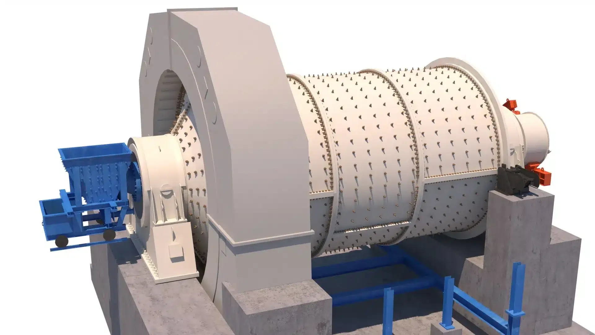
SAG-Mühlen (Semi-Autogenous Grinding) nutzen das Erz selbst als Mahlmedium, ergänzt durch eine geringe Stahlkugelfüllung (8–15 %). Die resultierende Kombination aus autogener Prallzerkleinerung und kugelunterstützter Attrition macht SAG-Mühlen zur tragenden Säule moderner Zerkleinerungskreisläufe — sie verarbeiten Roherz von 300 mm Aufgabegröße zu 10–25 mm Produkt in einer einzigen Stufe. SAG-Mühlen sind die größten rotierenden Mahlaggregate im Bergbau, mit Durchmessern bis zu 12,2 m (40 ft) und Antriebsleistungen von über 25 MW.
Jede Verschleißkomponente einer SAG-Mühle arbeitet unter extremen Bedingungen: Mantelauskleidungen absorbieren den Aufprall von Erzbrocken, die aus über 5 m Höhe herabstürzen, Hubleisten steuern eine kombinierte Füllung mit einem Gewicht von hunderten Tonnen, und Rostplatten müssen die Trübenabgabe mit der Pebble-Extraktion ausbalancieren. ATF entwickelt und fertigt das vollständige Sortiment an Auskleidungen, Hubleisten, Rostplatten und Austragskomponenten für SAG-Mühlen nach OEM-Spezifikationen — mit Legierungssorten, Profilgeometrien und Pebble-Port-Konfigurationen, die für Ihr spezifisches Erz und Ihren Mahlkreislauf optimiert sind.

ATF SAG-Mühlen-Auskleidungen — Mantelauskleidungen, hochprofilierte Hubleisten und Rostplatten mit Pebble-Ports in Chrom-Molybdän-Stahl und bimetallischen Konfigurationen, ausgelegt für die hochaufprallintensive halbautogene Mahlung.
Mechanismus der halbautogenen Mahlung
Das Verständnis, wie der Erz-auf-Erz-Aufprall, die kugelunterstützte Attrition und die Steuerung der Ladungstrajektorie zusammenwirken, erklärt, warum Auskleidungsprofil, Hubleistengeometrie und Rostdesign direkt die Mahleffizienz, den Energieverbrauch, den Durchsatz und die Kosten pro gemahlene Tonne bestimmen.
Aufgabe und Anhebung der Ladung
Das Roherz (bis zu 300 mm) gelangt durch den Aufgabezapfen zusammen mit den rezirkulierten Pebbles in die SAG-Mühle. Während sich die Mühle mit 70–78 % der kritischen Drehzahl dreht, transportieren hochprofilierte Hubleisten (200–350 mm) die kombinierte Ladung aus Erz und Stahlkugeln entlang der Mantelwand nach oben. Die Höhe und der Flächenwinkel der Hubleiste bestimmen den Schulterwinkel — wie hoch die Ladung angehoben wird, bevor sie sich von der Auskleidung löst und ihren Abstieg in Richtung Fußzone beginnt.
Mahlung durch Aufprall und Attrition
Das Erz wird durch zwei Mechanismen zerkleinert: Kataraktieren (große Erzbrocken und Stahlkugeln fallen frei durch die Luft und prallen in die Ladung — grobe Partikel werden gebrochen) und Kaskadieren (das Erz rollt über die Oberfläche der Ladung — Mahlung durch Abrieb und interpartikuläre Kompression). Das Gleichgewicht zwischen diesen Mechanismen wird durch Mühlendrehzahl, Hubleistenprofil, Kugelfüllung und Erzkompetenz gesteuert. Diese duale Mahlwirkung ermöglicht es SAG-Mühlen, ROM-Erz in einer einzigen Stufe zu verarbeiten.
Austrag und Pebble-Extraktion
Die gemahlene Trübe passiert die Öffnungen der Rostplatten (10–40 mm), während Pebbles kritischer Größe (50–100 mm) durch dedizierte Pebble-Ports (80–120 mm) extrahiert und zur weiteren Größenreduzierung an einen Pebble-Brecher gesendet werden, bevor sie zur Mühlenaufgabe zurückgeführt werden. Pulplifter-Kanäle transportieren die Trübe von der Rostfläche zum Austragszapfen. Ein Trommelsieb am Austrag klassiert das Produkt, bevor es zur nächsten Stufe weitergeleitet wird — typischerweise eine Kugelmühle oder ein Klassierungskreislauf.
SAG-Mühlen-Auskleidungen und Verschleißkomponenten
Eine SAG-Mühle benötigt fünf Kategorien von Verschleiß- und Strukturkomponenten. Jede Komponentenseite bietet detaillierte Werkstoffoptionen, Profildesign-Empfehlungen und OEM-Kompatibilitätsinformationen für Ihre spezifische Mühle.
Mantelauskleidungen
Schützen den zylindrischen Mantel vor dem direkten Aufprall großer Erzbrocken und Stahl-Mahlkörper. Die Mantelauskleidungen von SAG-Mühlen müssen weitaus höheren Aufprallenergien standhalten als die von Kugelmühlen — Erzstücke bis zu 300 mm treffen die Auskleidung beim Kataraktieren mit hoher Geschwindigkeit. Hochhebende und wellenförmige Profile steuern die Ladungstrajektorie und die Mahlwirkung.
Endauskleidungen
Schützen die Aufgabe- und Austragsböden der SAG-Mühle. Die aufgabeseitigen Endauskleidungen integrieren die Geometrie der Aufgabeöffnung und müssen dem direkten Aufprall des einströmenden Groberzes standhalten. Die austragsseitigen Endauskleidungen fügen sich in die Anordnung der Rostplatten ein und müssen die korrekte Geometrie für die Roststützung und die Pulplifter-Ausrichtung gewährleisten.
Hubleisten
Hochprofilierte erhabene Elemente, die die kombinierte Ladung aus Erz und Stahlkugeln anheben. Hubleisten für SAG-Mühlen sind deutlich höher als jene für Kugelmühlen (200–350 mm), um die größere und schwerere Ladung zu bewältigen. Hubleistenhöhe, Flächenwinkel und Reihenabstand steuern das Gleichgewicht zwischen Prallmahlung (Kataraktieren) und Attritionsmahlung (Kaskadieren) — und bestimmen so direkt Durchsatz und Energieeffizienz.
Rostplatten
Perforierte Austragsplatten, die Mahlkörper und Übergrößenerz zurückhalten und gleichzeitig gemahlene Trübe durchlassen. Die Roste von SAG-Mühlen verfügen sowohl über feine Öffnungen (10–40 mm) für den Produktaustrag als auch über Pebble-Ports (80–120 mm) zur Extraktion von Pebbles kritischer Größe, die zu einem Pebble-Brecher rezirkuliert werden. Die offene Rostfläche (8–25 %) steuert direkt die Durchsatzkapazität der Mühle.
Zusätzliche Ersatzteile
Trunnion-Auskleidungen, Pulplifter-Kanäle, Aufgabeschurren, Trommelsiebe und Mühlen-Schraubverbindungen. Diese Struktur- und Strömungssteuerungskomponenten erhalten die Mühlengeometrie, schützen hochwertige Strukturelemente und steuern den Materialaustrag. Insbesondere die Trunnion-Auskleidungen schützen die teuren und nicht austauschbaren Mühlenzapfen vor abrasivem Trübenverschleiß.
Werkstoffauswahl für SAG-Mühlen-Auskleidungen
Die Legierungsauswahl für SAG-Mühlen-Auskleidungen wird von der Schlagzähigkeit dominiert — die Energie von Erzbrocken und Stahlkugeln, die in einer Mühle mit 6–12 m Durchmesser katarktieren, ist weitaus höher als in einer Kugelmühle. Chrom-Molybdän-Stahl ist der Standard, weil er diese Energie ohne Rissbildung absorbiert. Bimetallische und hochchromhaltige Legierungen werden gezielt an Positionen mit geringerem Aufprall eingesetzt, um die Standzeit zu verlängern.
Chrom-Molybdän-Stahl
Cr-Mo alloy steel (325–450 BHN)
Der Industriestandard für Mantelauskleidungen und Hubleisten von SAG-Mühlen — bewährte Zähigkeit, um dem hochenergetischen Aufprall von Großerz und Stahlkugeln mit 125 mm standzuhalten
Referenz (typisch 4–12 Monate)
Einschränkung: Höhere Verschleißrate als bimetallisch oder Hochchrom in rein abrasiven Zonen — die Aufpralltoleranz ist jedoch in SAG-Mühlen unverzichtbar
Bimetallisch (Cr-Mo + HCWI)
Chrome-moly backing with high-chrome white iron face (600+ BHN)
Hochverschleißzonen im unteren Mantel, wo Abrasion dominiert — die harte Weißguss-Schicht widersteht abrasivem Verschleiß, während der Chrom-Molybdän-Träger die Aufprallenergie absorbiert
1,5–2,5× Chrom-Molybdän an geeigneten Positionen
Einschränkung: Höhere Kosten als Standard-Chrom-Molybdän. Die Weißguss-Schicht kann unter extremem Punktlast-Aufprall sehr großer Erzbrocken in der Kataraktier-Zone reißen
Hochchromhaltiger Weißguss
25–28% Cr (58–64 HRC)
Rostplatten und Austragskomponenten, bei denen die Abrasion hoch, aber der direkte Mahlkörperaufprall begrenzt ist. Nicht geeignet für Mantelauskleidungen oder Hubleisten von SAG-Mühlen
1,5–2× Chrom-Molybdän nur an Rostpositionen
Einschränkung: Sehr spröde unter den hochenergetischen Aufpralllasten in einer SAG-Mühle — reißt oder zerbricht in Mantel- oder Hubleistenpositionen
Ni-Hard / Legierter Guss
Ni-Cr alloy iron (550–650 BHN)
Rostplatten, Pulplifter-Kanäle und Komponenten des Austragsendes, bei denen eine moderate Aufprallfestigkeit akzeptabel ist
1,3–1,8× Chrom-Molybdän in Austragskomponenten
Einschränkung: Nicht empfohlen für Mantelauskleidungen oder Hubleisten in SAG-Mühlen — unzureichende Zähigkeit für die hochenergetische Kataraktier-Aufprallzone
Leitfaden zur Legierungsauswahl für SAG-Mühlen
Mantelauskleidungen und Hubleisten (alle Positionen)? → Chrom-Molybdän-Stahl (400–450 BHN) — unverzichtbar für die Aufprallfestigkeit der SAG-Mühle
Untere Mantelauskleidungen in stark abrasivem Erz? → Bimetallisch (Cr-Mo + HCWI-Schicht) für 1,5–2,5× Standzeit in der Gleitverschleißzone
Rostplatten und Austragskomponenten? → Hochchromhaltiger Weißguss oder Ni-Hard für maximale Abriebfestigkeit an Positionen mit geringem Aufprall
Endauskleidungen (Aufgabe- und Austragsboden)? → Chrom-Molybdän-Stahl (350–400 BHN) — moderater Aufprall bei guter Abriebfestigkeit
Kontaktieren Sie ATF mit Ihrer Mühlengröße, dem Abrasionsindex des Erzes (Ai), dem Bond-Arbeitsindex (Wi), dem Kugelfüllgrad und den aktuellen Leistungsdaten der Auskleidung — wir empfehlen die optimale Legierungs- und Profilkombination für jede Position Ihrer SAG-Mühle.
Kompatible SAG-Mühlen-Marken und -Modelle
ATF fertigt Aftermarket-Mantelauskleidungen, Hubleisten, Endauskleidungen und Rostplatten nach OEM-Maß- und Profilspezifikationen für SAG-Mühlen aller großen Hersteller. Alle Auskleidungen werden vor der Produktion anhand der Original-Mühlenzeichnungen geprüft. Maßtoleranz: ±2 mm für Schraubenlochpositionen, Gewicht: ±3 %.
Metso / Outotec
SAG-Mühlen von 6,1 m bis 12,2 m Durchmesser — einschließlich Nordberg- und Outotec-Designs
Einschließlich Legacy-Designs von Nordberg, Svedala und Outotec-SAG-Mühlen
FLSmidth
SAG-Mühlen von 6,1 m bis 12,2 m Durchmesser — einschließlich Fuller-Traylor-Designs
Einschließlich SAG-Mühlen-Designs von ABON, Fuller-Traylor und Legacy Allis-Chalmers
Thyssenkrupp / Polysius
SAG-Mühlen von 6,0 m bis 11,6 m Durchmesser — Polysius und industrielle Mahlsysteme
ThyssenKrupp Industrial Solutions — SAG-Mühlen mit großem Durchmesser für den Bergbau
CITIC
SAG-Mühlen von 6,1 m bis 12,2 m Durchmesser — großdimensionierte Mühlen für die Mineralaufbereitung
CITIC Heavy Industries — weit verbreitet in Kupfer-, Gold- und Eisenerz-Betrieben
Outotec (Legacy)
Legacy-Designs von Outotec-SAG-Mühlen — verschiedene Durchmesser bis zu 12,2 m
Heute Metso Outotec — Originalmodelle und -zeichnungen werden für Legacy-Mühlen gepflegt
Others
Svedala, Dominion, Hardinge, KHD, Marcy, Denver, Allis-Chalmers
Kontaktieren Sie ATF mit den Typenschilddaten der Mühle zur Bestätigung der Auskleidungspassform
Ihren SAG-Mühlen-Hersteller nicht gefunden? ATF pflegt Zeichnungen und Modelle für SAG-Mühlen aller großen und Legacy-Hersteller. Senden Sie die Typenschilddaten Ihrer Mühle, Zeichnungen oder Auskleidungsmaße zur Passformbestätigung.
Ihre Mühle verifizierenPlanen Sie eine Neuauskleidung Ihrer SAG-Mühle?
Senden Sie Ihre Mühlenspezifikationen, die aktuelle Auskleidungskonfiguration und den Wechselplan für ein umfassendes Angebot. ATF kann Legierungs- und Profiloptimierungen empfehlen — einschließlich bimetallischer Optionen und Pebble-Port-Dimensionierung — um die Auskleidungsstandzeit zu verlängern und die Mahleffizienz zu verbessern.
Best Practices für die Wartung von SAG-Mühlen-Auskleidungen
Neuauskleidungen von SAG-Mühlen gehören zu den teuersten und zeitkritischsten Wartungsereignissen in einer Bergbauanlage. Eine disziplinierte Auskleidungsüberwachung verlängert die Wechselintervalle, verhindert ungeplante Stillstände und erhält den Durchsatz des Mahlkreislaufs. Eine verschlissene Hubleiste in einer SAG-Mühle verändert die Ladungstrajektorie für hunderte Tonnen Material.
Jede Schicht
- Mühlenleistungsaufnahme überwachen — plötzliche Abfälle deuten auf Auskleidungsversagen, Veränderungen des Ladungsniveaus oder Zusetzen der Pebble-Ports hin
- Mühlenlagertemperaturen und Schmierdruck prüfen — die Lager von SAG-Mühlen tragen extreme Lasten
- Auf ungewöhnliche Geräusche achten: wiederholtes metallisches Hämmern deutet auf eine verschobene Auskleidung oder eine gebrochene Hubleiste hin
- Aufgaberate des Pebble-Brechers überwachen — Veränderungen deuten auf den Zustand der Pebble-Ports der Roste hin
Wöchentlich
- Produktpartikelgröße beproben und analysieren — Abweichungen deuten auf Auskleidungs-/Hubleistenverschleiß hin, der die Ladungstrajektorie beeinflusst
- Zustand des Trommelsiebs inspizieren — zerrissene oder zugesetzte Siebe reduzieren die Klassiereffizienz
- Trunnion-Auskleidungen von Aufgabe und Austrag auf Verschleiß oder Trübenflussbeschränkungen prüfen
- Durchsatzdaten der Pebble-Ports auf Anzeichen von Zusetzen oder Aufweitung überprüfen
Monatlich
- Mantelauskleidungsdicke an mehreren Punkten mit Ultraschall-Messgeräten messen — das umfangs- und axialseitige Verschleißmuster kartieren
- Hubleistenhöhen über die gesamte Mühlenlänge inspizieren — verschlissene Hubleisten verändern die Ladungstrajektorie und reduzieren die Aufprallenergie
- Schraubenspannung an zugänglichen Mühlenverbindungen prüfen — Vibration und thermische Zyklen der SAG-Mühle lockern Verbindungselemente
- Rostplatten durch die Inspektionsöffnungen auf Risse, Durchverschleiß oder Aufweitung der Pebble-Ports prüfen
Beim Auskleidungswechsel (Reline)
- Mühlenmantel auf Erosion, Risse oder Korrosion unter den Auskleidungsplatten inspizieren — insbesondere im Bereich der Schraubenlöcher
- Alle Rostplatten prüfen — alle mit verschlissenen, gerissenen oder aufgeweiteten Öffnungen oder Pebble-Ports austauschen
- Sicherstellen, dass Hubleistenhöhen und Flächenwinkel der ursprünglichen Designspezifikation für Ihre Ladungstrajektorie entsprechen
- Pulplifter-Kanäle auf Verstopfung, Durchverschleiß oder Korrosion inspizieren
- Alle Mühlenschrauben austauschen — niemals gelängte oder korrodierte Verbindungselemente in einer hochenergetischen SAG-Mühle wiederverwenden
- Zustand der Trunnion-Auskleidung inspizieren — Trunnion-Schäden durch Auskleidungsversagen sind extrem kostspielig zu reparieren
Typische Betriebsparameter von SAG-Mühlen
| Parameter | Standard-SAG | SAG mit hohem Verhältnis |
|---|---|---|
| Mühlendurchmesser | 6.1–9.8 m (20–32 ft) | 9.8–12.2 m (32–40 ft) |
| Mühlendrehzahl | 72–76% critical | 70–74% critical |
| Kugelfüllung | 10–15% fill | 8–12% fill |
| Gesamtfüllung | 25–35% fill | 25–30% fill |
| Kugelgröße | 100–125 mm | 125 mm |
| Hubleistenhöhe | 200–300 mm | 250–350 mm |
| Auskleidungslegierung | Cr-Mo (400–450 BHN) | Cr-Mo / Bimetallic |
Die Parameter sind Richtwerte. Optimale Einstellungen hängen von den Mühlenabmessungen, Erzcharakteristiken, der Kugelfüllstrategie und dem Design des Mahlkreislaufs ab. SAG-Mühlen mit hohem Aspektverhältnis (D/L > 2) arbeiten anders als konventionelle SAG-Mühlen. Konsultieren Sie stets Ihren Verfahrensingenieur für standortspezifische Empfehlungen.
Häufige Probleme bei SAG-Mühlen und Lösungen
Auskleidungsprobleme bei SAG-Mühlen haben unmittelbare und erhebliche Auswirkungen auf den Durchsatz des Mahlkreislaufs. Das frühzeitige Erkennen von Verschleißmustern und Betriebssymptomen verhindert Produktionsverluste, ungeplante Auskleidungswechsel und Schäden am Mühlenmantel. Kontaktieren Sie den technischen Support von ATF, wenn Sie Hilfe bei der Diagnose eines Problems an einer SAG-Mühle benötigen.
Gröberes Produkt / Verlust der Mahleffizienz
Wahrscheinliche Ursachen
- Hubleisten unterhalb der effektiven Höhe verschlissen — die Ladung wird nicht in die korrekte Aufprallzone katarktiert
- Mantelauskleidungen glatt verschlissen — das verlorene hochhebende Profil reduziert die Anhebewirkung der Ladung
- Rostöffnungen durch nahmaßiges Material, Fremdmetall oder verformte Kugeln zugesetzt
- Pebble-Ports zugesetzt — Pebbles kritischer Größe sammeln sich in der Ladung an, statt extrahiert zu werden
Korrekturmaßnahmen
- Hubleistenhöhen messen und mit der Originalspezifikation vergleichen — austauschen, wenn unter der minimalen effektiven Höhe
- Mantelauskleidungsprofile inspizieren — glatt verschlissene Auskleidungen verlieren ihre Mahlwirkung unabhängig von der Restdicke
- Rostplatten reinigen und inspizieren — alle mit zugesetzten, aufgeweiteten oder gerissenen Öffnungen austauschen
- Zustand der Pebble-Ports und Betrieb des Pebble-Brecher-Kreislaufs überprüfen — jede Blockade beseitigen
Risse oder Bruch der Auskleidung
Wahrscheinliche Ursachen
- Aufprallenergie überschreitet die Zähigkeit der Legierung — übergroßes Erz oder zu große Kugeln für die Auskleidungssorte
- Versagen der Mühlenschrauben ermöglicht Auskleidungsbewegung — zyklische Belastung erzeugt Ermüdungsrisse in nicht gestützten Platten
- Thermische Spannung durch Temperaturunterschiede bei Anfahr-/Abschaltvorgängen in den schweren Auskleidungsgussstücken
- Falsches Auskleidungsprofil erzeugt Punktlast-Aufprall statt verteiltem Ladungskontakt
Korrekturmaßnahmen
- Legierungsauswahl überprüfen — Chrom-Molybdän-Stahl (400+ BHN) für die Aufprallzonen der SAG-Mühle, bimetallisch nur im unteren Mantel
- Alle Mühlenschrauben prüfen und nachziehen — alle mit Längung, Gewindeschäden oder Korrosion austauschen
- Stufenweise Drehzahlerhöhung der Mühle beim Anfahren einführen, um den Thermoschock auf die Auskleidungsgussstücke zu reduzieren
- Profilgeometrie der Auskleidung gegen das empfohlene Design für Ihre Mühlengröße und Ladungstrajektorie überprüfen
Übermäßige Mühlenvibration
Wahrscheinliche Ursachen
- Verschobene oder gebrochene Auskleidungsplatte erzeugt eine unausgewuchtete rotierende Masse
- Ungleichmäßige Ladungsverteilung — Materialsegregation oder bevorzugte Beladung durch das Aufgabesystem
- Verschlissene Zapfenlager oder Verlagerung der Mühlenausrichtung — die Masse der SAG-Mühle verstärkt jede Unwucht
Korrekturmaßnahmen
- Mühle stoppen und Inneres auf verschobene Auskleidungen inspizieren — in einer SAG-Mühle kann eine verschobene Auskleidung ein Kaskadenversagen benachbarter Platten auslösen
- Aufgabenverteilung und Ladungsniveau überprüfen — korrekten Füllgrad (25–35 %) und Kugel-zu-Erz-Verhältnis sicherstellen
- Spiel der Zapfenlager und Mühlenausrichtung prüfen — bei Bedarf nacharbeiten oder austauschen
Reduzierter Mühlendurchsatz
Wahrscheinliche Ursachen
- Rostplatten teilweise zugesetzt — Trüben- und Pebble-Austrag eingeschränkt, was zu Aufstauung in der Mühle führt
- Pulplifter-Kanäle durch übergroße Mahlkörper, gebrochene Auskleidungsfragmente oder Fremdmaterial blockiert
- Anreicherung von Pebbles kritischer Größe — Pebbles zu groß zum Mahlen und zu klein zum effektiven Kataraktieren
Korrekturmaßnahmen
- Rostplatten inspizieren und reinigen — alle mit verschlissenen oder zugesetzten Öffnungen oder Pebble-Ports austauschen
- Pulplifter-Kanäle freimachen und auf strukturelle Schäden oder Durchverschleiß inspizieren
- Dimensionierung der Pebble-Ports und Pebble-Brecher-Kreislauf überprüfen — sicherstellen, dass Pebbles kritischer Größe extrahiert und rezirkuliert werden
Übermäßige Auskleidungsverschleißrate
Wahrscheinliche Ursachen
- Auskleidungslegierung nicht auf Erzabrasivität und Aufprallenergie abgestimmt — zu weich für die Anwendung
- Mühlendrehzahl zu hoch — übermäßiges Kataraktieren beschleunigt den Verschleiß der Auskleidungsoberfläche
- Kugelfüllung zu hoch — überschüssige Stahl-Mahlkörper erzeugen mehr Stahl-auf-Auskleidung-Aufprall als ausgelegt
- Aufgabegröße zu groß — übergroße Erzbrocken konzentrieren die Aufprallenergie auf einzelne Auskleidungsplatten
Korrekturmaßnahmen
- Auskleidungslegierung gegen den Erzabrasionsindex (Ai) und den Bond-Arbeitsindex (Wi) überprüfen — bimetallisch für Hochverschleißzonen in Betracht ziehen
- Mühlendrehzahl als Prozentsatz der kritischen Drehzahl verifizieren — anpassen, falls außerhalb des empfohlenen Bereichs (typisch 70–78 % für SAG)
- Kugelfüllvolumen und Kugelgrößenverteilung überprüfen — typisch 8–15 % Kugelfüllung für SAG-Mühlen
- Kontrolle der Aufgabegröße prüfen — übergroßes Aufgabematerial sollte vor der Mühle gesiebt oder abgeschöpft werden
Häufig gestellte Fragen
Antworten auf häufige Fragen zu SAG-Mühlen-Auskleidungen, Werkstoffauswahl, Pebble-Port-Design, Wartung und Bestellung. Nicht gefunden, wonach Sie suchen?
Unser Team kontaktierenWas ist der Unterschied zwischen einer SAG-Mühle und einer Kugelmühle?
Warum sind Auskleidungen von SAG-Mühlen so viel schwerer als die von Kugelmühlen?
Was sind Pebble-Ports und warum benötigen SAG-Mühlen sie?
Wie wähle ich zwischen Chrom-Molybdän- und bimetallischen SAG-Mühlen-Auskleidungen?
Wie oft sollten SAG-Mühlen-Auskleidungen ausgetauscht werden?
Welche Informationen benötigt ATF, um SAG-Mühlen-Teile anzubieten?
Sind ATF SAG-Mühlen-Teile mit OEM-Ausrüstung kompatibel?
Wie ist die typische Lieferzeit für SAG-Mühlen-Teile?
Bereit, die Leistung Ihrer SAG-Mühle zu optimieren?
ATF-Ingenieure antworten innerhalb von 24 Stunden mit Legierungsempfehlungen, Auskleidungsprofil-Verifizierung, Pebble-Port-Dimensionierungshinweisen und wettbewerbsfähigen Preisen für Ihre spezifische SAG-Mühle und Ihren Mahlkreislauf.
Kostenloses Angebot anfordernFordern Sie Noch Heute ein Kostenloses Angebot An
Unser Ingenieurteam antwortet innerhalb von 24 Stunden mit detaillierten Spezifikationen, Materialempfehlungen und wettbewerbsfähigen Preisen.