

Peças para Britador VSI
Peças para Britador VSI | Desgaste e Rotores | ATF
Peças para britadores VSI para aplicações rock-on-rock e rock-on-iron. Opções em carbeto de tungstênio, cerâmica e aço liga.
Complete Wear Part Solutions for VSI Crushers
Vertical Shaft Impact (VSI) crushers use a high-speed rotor to accelerate feed material to 60–80 m/s, ejecting it against either a self-forming rock shelf (rock-on-rock) or fixed anvil ring segments (rock-on-iron). This velocity-based crushing mechanism produces superior cubical product shape — making VSI crushers the industry standard for manufactured sand production, fine aggregate shaping and tertiary/quaternary size reduction.
Every wear component in a VSI crusher — from the rotor tips that accelerate material to the feed tube that controls entry distribution — operates under extreme velocity and abrasion conditions. Tip material selection, rotor balance, feed tube condition and wear plate integrity all interact to determine product quality, throughput and operating cost. ATF engineers and manufactures the complete range of VSI wear parts and spare components to OEM specifications, with material options optimised for your specific feed conditions and crushing mode.
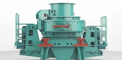
ATF VSI crusher wear parts — rotor tips, wear plates and anvil components in tungsten carbide, ceramic composite and alloy steel configurations.
VSI Crushing Mechanism
Understanding how each component contributes to the high-velocity crushing process explains why tip material selection, rotor balance and feed tube condition directly affect product shape, throughput and wear cost.
Feed Entry & Acceleration
Material enters the VSI through a vertical feed tube positioned centrally above the rotor. The feed tube directs material onto the distribution plate at the centre of the spinning rotor. Centrifugal force accelerates the material outward along the rotor channels toward the rotor tips. Feed tube alignment and condition are critical — a worn or off-centre tube causes uneven rotor loading and tip wear.
High-Velocity Impact
Material exits the rotor at the tips at 60–80 m/s and collides with either a rock shelf (rock-on-rock mode) or fixed anvil ring segments (rock-on-iron mode). The kinetic energy of this collision fractures the material through inter-particle or particle-to-anvil impact. Rock-on-rock produces the best cubical shape; rock-on-iron provides higher reduction ratios and more aggressive shaping.
Product Discharge
Crushed material falls by gravity to the bottom of the crushing chamber and discharges onto the conveyor. The upper and lower wear plates protect the housing during this process. Product gradation is controlled primarily by rotor speed (higher speed = finer product) and feed rate. VSI crushers typically achieve 3:1 to 5:1 reduction ratios, producing well-shaped aggregate and manufactured sand.
VSI Crusher Wear Parts & Spare Components
A VSI crusher requires three main categories of wear and spare components. Each component page provides detailed material options, OEM compatibility tables and application-specific guidance.
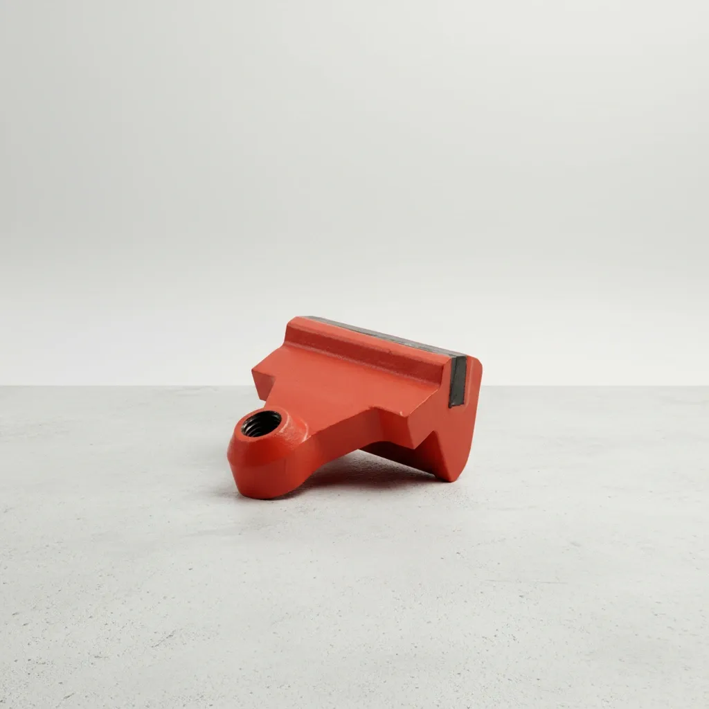
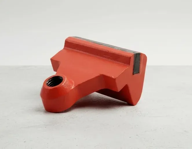
Rotor Tips & Anvils
The primary wear element in every VSI crusher. Rotor tips (also called rotor shoes or hammers) are mounted at the outer edge of the spinning rotor and accelerate material to 60–80 m/s before ejecting it against the anvil ring or rock shelf. Tungsten carbide (WC), ceramic composite and alloy steel options are available — material selection determines wear life, product shape and cost per ton.
Cavity Wear Plates
Protect the rotor cavity, upper and lower housing from high-velocity abrasive material flow. Cavity wear plates (upper, lower and distribution plates) absorb ricocheting material that would otherwise erode the cast housing. Worn wear plates expose structural components to irreversible damage.

Additional Spares
Feed tubes, feed eye rings, distribution plates and anvil ring segments. These components control material flow into and through the rotor, and form the impact surface in rock-on-iron configurations. Worn feed tubes cause off-centre rotor loading; damaged anvil segments reduce product quality and allow housing damage.
Material Selection for VSI Crusher Wear Parts
VSI crushers operate at the highest wear velocities of any crusher type — 60–80 m/s. Material selection must balance extreme abrasion resistance against impact toughness. The right material depends on feed cleanliness, abrasiveness and whether tramp metal events are possible. Using the wrong material doesn't just reduce wear life — it can destroy the rotor.
Tungsten Carbide (WC)
WC-Co composite (various carbide grain sizes)
High-velocity rotor tips in clean, abrasive feeds — manufactured sand, granite, basalt aggregate shaping
3–5× alloy steel tips
Limitation: Carbide tips can fracture under heavy tramp metal impact — requires effective metal detection upstream
Ceramic Composite (Al₂O₃-ZrO₂)
Alumina-zirconia inserts in alloy steel body
Ultra-abrasive clean feeds where maximum wear life justifies higher cost — silica sand, quartzite
4–6× alloy steel in ultra-abrasive feeds
Limitation: Ceramic inserts spall under point-load or tramp metal impact — strictly clean-feed applications only
High-Chrome Iron
25–28% Cr, 60–64 HRC
Anvil ring segments and wear plates in abrasive secondary/tertiary applications with controlled feed
2–3× alloy steel in clean abrasive feeds
Limitation: Brittle — shatters under direct tramp metal or high point-load impact at rotor tip speed
Alloy Steel (Martensitic)
48–54 HRC martensitic steel
General-purpose rotor tips and wear plates where feed contains occasional tramp metal or variable hardness
Baseline
Limitation: Shorter wear life than carbide or ceramic in highly abrasive feeds — higher replacement frequency
Quick Selection Framework
Clean, prescreened abrasive feed (sand, granite, basalt)? → Tungsten carbide rotor tips for maximum wear life
Ultra-abrasive clean feed (quartzite, silica)? → Ceramic composite for 4–6× wear life vs. alloy steel
Variable feed with possible tramp metal? → Alloy steel (martensitic) tips — impact-tough, lower wear life but won't shatter
Anvil segments (rock-on-iron)? → High-chrome iron for abrasion resistance in the impact zone
Not sure which material applies? Contact ATF with your crusher model, feed material, rotor speed and crushing mode — we'll recommend the optimal configuration.
Compatible VSI Crusher Brands & Models
ATF manufactures aftermarket rotor tips, wear plates, feed tubes and anvil segments to OEM dimensional specifications. All parts are verified against original drawings before production. Dimensional tolerance: ±0.5 mm on critical surfaces, weight: ±50g on rotor tips.
Metso
Barmac B5100, B6150, B7150, B9100, CV116, CV117, CV118, CV228, CV229
Barmac B-series and CV series — the original rock-on-rock VSI
Sandvik
CV215, CV217, CV218, CV228, CV229, QI442 HST
Sandvik stationary CV and mobile QI series
Terex / Cedarapids
Canica VSI 65, 95, 105, 120, 150, 2050, 2350, 2500
Canica vertical shaft impactors
Kleemann
EVO series mobile VSI crushers
Wirtgen Group mobile VSI platforms
REMco
REMco 9000ST, 9000VST, SandMax series
SandMax and ST series autogenous VSI crushers
Trio / Weir
TV85, TV105, APP series
Trio and Weir Minerals VSI models
Don't see your crusher model? ATF maintains drawings and patterns for VSI crushers from all major manufacturers including discontinued and legacy equipment. Send your crusher nameplate or part number for confirmation.
Verify Your ModelNeed VSI Crusher Parts Fast?
Stock rotor tips and common wear parts ship within 1–2 weeks. Send your crusher model, rotor configuration and part requirements for a same-day quotation.
VSI Crusher Maintenance Best Practices
VSI crushers operate at the highest wear velocities of any crusher type. Disciplined maintenance extends tip life, prevents catastrophic rotor imbalance and protects bearings, seals and the crusher housing from damage caused by worn or unbalanced components.
Every Shift
- Check rotor tip wear visually through access doors — uneven wear indicates feed or balance issues
- Listen for abnormal vibration or rattling — can indicate loose tips, broken anvils or unbalanced rotor
- Verify feed rate and distribution — material must enter centrally through the feed tube for even tip wear
Weekly
- Measure rotor tip wear at all positions — tips must be within weight tolerance for rotor balance
- Inspect feed tube for wear-through — a worn feed tube allows off-centre feeding that destroys tips unevenly
- Check anvil ring segments (rock-on-iron) for grooving, cracking or through-wear
Monthly
- Weigh all rotor tips — opposing tips must be matched within ±50g to prevent destructive vibration
- Inspect upper and lower wear plates for breakthrough approaching the housing casting
- Check feed eye ring condition — worn feed eyes allow material to erode the rotor top plate
At Tip Rotation / Replacement
- Rotate tips to unworn faces at 30–50% wear (most tips have 2–4 usable faces)
- Weigh all tips before installing — match opposing positions within ±50g for balance
- Inspect rotor body for cracks, erosion and tip seat condition — replace damaged tip seats
- Replace the feed tube if worn past 50% of wall thickness — prevents catastrophic tip failure from off-centre feed
- Check distribution plate condition and replace if eroded — affects material flow pattern into rotor
Typical VSI Operating Parameters by Application
| Application | Tip Speed | Mode | Tip Material |
|---|---|---|---|
| Manufactured Sand | 65–80 m/s | Rock-on-Rock | Tungsten Carbide |
| Aggregate Shaping | 55–70 m/s | Rock-on-Rock | WC or Alloy Steel |
| Tertiary Crushing | 60–75 m/s | Rock-on-Iron | WC tips / Chrome anvils |
| Recycling / Mixed Feed | 50–65 m/s | Rock-on-Iron | Alloy Steel (martensitic) |
Parameters are indicative. Optimal speed depends on crusher model, feed material and target product specification. Always refer to your OEM manual for model-specific limits.
Common VSI Crusher Problems & Solutions
At 60–80 m/s tip speed, VSI crusher problems escalate rapidly. Recognising wear patterns and operational symptoms early prevents catastrophic rotor failure, bearing damage and housing erosion. Contact ATF technical support if you need help diagnosing an issue.
Uneven Rotor Tip Wear
Probable Causes
- Off-centre feed — worn or damaged feed tube directing material asymmetrically into the rotor
- One or more tips are lighter/heavier than opposing tips — weight imbalance causes preferential loading
- Anvil ring segments worn unevenly, creating asymmetric rebound patterns (rock-on-iron mode)
Corrective Actions
- Inspect and replace feed tube if worn — material must enter the rotor dead-centre
- Weigh all tips and match opposing positions within ±50g
- Replace worn anvil segments to restore uniform impact surface around the full circumference
Rotor Tip Breakage / Carbide Fracture
Probable Causes
- Tramp metal (steel, rock bolts, drill bits) entering at rotor tip speed — catastrophic impact
- Oversized feed exceeding the rotor's design capacity — point-load stress on tip edges
- Wrong tip material for the application — brittle carbide used where feed contains unpredictable tramp
Corrective Actions
- Install or upgrade metal detection and removal upstream of the VSI crusher
- Screen feed to remove oversize material before the crusher — respect maximum feed size for your model
- Switch to alloy steel or martensitic tips if tramp metal events are unavoidable
Poor Product Shape (Flaky / Elongated)
Probable Causes
- Rotor speed too low — insufficient velocity to achieve inter-particle crushing
- Rock shelf (autogenous mode) not maintained — too little material build-up on shelf
- Anvil ring worn smooth — no angular impact surface to promote cubical fracture
Corrective Actions
- Increase rotor speed within OEM limits — higher velocity produces better cubical shape
- Maintain cascading feed rate to keep the rock shelf full in rock-on-rock mode
- Replace worn anvil ring segments — fresh angular surfaces improve product shape
Excessive Vibration
Probable Causes
- Weight imbalance between opposing rotor tips — even small differences amplify at 60–80 m/s
- Broken or missing tip on one side of the rotor — extreme imbalance
- Feed tube misalignment causing uneven material loading across the rotor
Corrective Actions
- Stop immediately if vibration is sudden — check for broken tips before restarting
- Weigh all tips and match opposing positions within ±50g
- Centre the feed tube and verify it is not worn or deformed
Reduced Throughput / Excessive Fines
Probable Causes
- Tips worn past effective profile — material slides past instead of being accelerated
- Rotor speed too high for the application — over-crushing producing excess fines
- Worn wear plates allowing material recirculation instead of clean discharge
Corrective Actions
- Replace tips when worn beyond rotation limits — flat tips lose acceleration efficiency
- Reduce rotor speed to control fines production — balance speed against product shape requirements
- Replace worn upper and lower wear plates to restore correct material flow paths
Frequently Asked Questions
Answers to common questions about VSI crusher parts, material selection, maintenance and ordering. Can't find what you're looking for?
Contact Our TeamWhat is the difference between rock-on-rock and rock-on-iron VSI crushing?
What rotor tip material should I use?
How does rotor speed affect VSI crusher performance?
Why is rotor balance so critical in a VSI crusher?
How often should VSI rotor tips be rotated?
Are ATF VSI crusher parts compatible with OEM equipment?
What information does ATF need to quote VSI crusher parts?
What is the typical lead time for VSI crusher parts?
Ready to Optimise Your VSI Crusher Performance?
ATF engineers respond within 24 hours with material recommendations, rotor configuration verification and competitive pricing for your specific VSI crusher and application.
Request a Free QuoteSolicite um Orçamento Gratuito Hoje
Nossa equipe de engenharia responde em 24 horas com especificações detalhadas, recomendações de materiais e preços competitivos.