

Technische Eckdaten
- Material Grades
- Cr-Mo Steel (325–450 BHN), Mn Steel (Mn14Cr2)
- Manganese Hardness
- 200 BHN initial, work-hardens to 500+ BHN
- Piece Weight
- 500–5,000 kg (diameter-dependent)
- Mill Compatibility
- 6 m – 12 m diameter SAG mills
- Segments per Head
- 6–16 pieces (mill-size dependent)
- Section Thickness
- 100–200 mm (heavier than ball mill heads)
- Bolt Grades
- Grade 10.9–12.9 (ISO 898-1)
SAG Mill End Liners: Heavy-Duty Head Protection
SAG mill end liners (head liners) protect the feed and discharge heads from the severe impact loading created by the tumbling charge of run-of-mine ore and large grinding balls weighing 100–150 mm in diameter. The feed-end liner must survive direct impact from large ore chunks—up to 300 mm—entering through the feed trunnion, making it one of the highest-wear positions in the entire mill. The discharge-end liner works in conjunction with the grate system to control product exit while shielding the head from the grinding charge. ATF manufactures SAG mill end liners from chrome-moly steel at 325–450 BHN for applications demanding a balance of wear resistance and toughness, and from austenitic manganese steel (Mn14Cr2, conforming to ASTM A128 Grade C) at 200 BHN initial hardness that work-hardens to 500+ BHN under impact, providing exceptional resistance in extremely high-impact zones.
SAG mill end liners require substantially heavier construction than ball mill equivalents due to the larger charge mass and significantly higher impact energies inherent in primary grinding duty. Section thicknesses typically range from 100 mm to 200 mm—double that of many ball mill end liners—to provide adequate material for both wear allowance and structural integrity. Feed-end designs incorporate deflector features and optimised cone angles to redirect incoming ore into the active grinding zone while distributing impact loads across the full head surface rather than concentrating them on localised areas. Discharge-end designs integrate precisely with grate panels, pebble port assemblies, and pulp lifter channels to ensure smooth material flow and efficient product removal without dead zones. ATF engineers end liner systems matched to each specific SAG mill configuration, using 3D modelling and field performance data to optimise profile geometry, segment count (typically 6–16 pieces per head), and material selection.
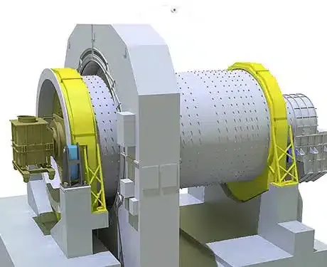
Feed and discharge end liners for SAG mills — designed for oversized ore feed and high media charge impacts
Key Features of ATF SAG Mill End Liners
Feed-End Protection
Robust feed-end liners designed to deflect and distribute impact from large ore chunks entering the mill.
Discharge-End Integration
Discharge-end liners engineered to work seamlessly with grate panels and pulp lifter assemblies.
Heavy Section Construction
Increased section thickness compared to ball mill end liners to withstand SAG mill impact loading.
Chrome-Moly Alloy Steel
Impact-resistant chrome-moly steel (325-400 BHN) for extended service life under severe conditions.
Lifting Provisions
Integral lifting points and handling features for safe installation of large, heavy components.
Cone Angle Optimization
Head liner cone angles designed to optimize charge dynamics and material flow.
Material Options for SAG Mill End Liners
SAG mill end liner material must provide impact toughness to survive the severe loading conditions at the mill heads while resisting abrasive wear.
| Werkstoff | Härte | Anwendung | Hinweise |
|---|---|---|---|
| Chrome-Moly Steel (Standard) | 325-370 BHN | General SAG mill applications | Excellent impact toughness, good wear life |
| Chrome-Moly Steel (High-Hard) | 400-450 BHN | Abrasive ores with moderate impact loading | Improved wear resistance |
| Manganese Steel | 200 BHN initial, work hardens to 500+ | Extremely high impact zones | Work hardening provides impact resistance |
Chrome-Moly Steel (Standard)
Chrome-Moly Steel (High-Hard)
Manganese Steel
Note: End liner material typically matches or is slightly softer than shell liner material to prioritize impact resistance at the heads.
Need SAG Mill End Liners?
Send your mill specifications for feed and discharge end liner quotations.
OEM Compatibility
ATF manufactures end liners for all major SAG mill brands with correct head profiles and mounting configurations.
Metso Outotec
- All SAG mill sizes
FLSmidth
- All SAG mill sizes
- Fuller-Traylor Mills
ThyssenKrupp
- All SAG mill sizes
CITIC
- All SAG mill sizes
Outotec (legacy)
- All SAG mill sizes
Custom Mills
- Any SAG mill make and size
End Liners FAQ
Finden Sie Antworten auf häufige Fragen zu end liners Werkstoffen, Auswahl, Wartung und Bestellung. Nicht gefunden, was Sie suchen?
Unser Team kontaktierenDo SAG mill end liners wear faster than shell liners?
Why is the feed-end liner design different from ball mills?
Can end liners be replaced during a partial reline?
How do discharge-end liners integrate with the grate system?
Technischer Inhalt geprüft vom ATF-Ingenieurteam | Metallurgische Spezifikationen verifiziert nach ASTM/ISO-Normen
Get a Quote for SAG Mill End Liners
Provide your mill specifications for quotation on feed and discharge end liners.
Contact ATF Engineering