

Repuestos para Planta de Cemento
Piezas de Enfriador de Clínker | Repuestos de Cemento | ATF
Piezas de enfriador de clínker: placas de parrilla, travesaños y revestimientos de pared. Aleaciones resistentes al calor para ciclaje térmico 100-1400 C.
Clinker Cooler Components for Cement Plants
Clinker coolers represent one of the most demanding thermal environments in cement manufacturing. Hot clinker exits the rotary kiln at 1,200–1,400°C and must be cooled rapidly to 65–100°C for downstream handling, storage and cement grinding. Grate plates, crossbars and wall liners face continuous thermal cycling with temperature differentials exceeding 1,000°C across the cooler length — combined with severe abrasion from moving clinker nodules and oxidising atmospheres that attack metal surfaces through high-temperature scaling.
ATF clinker cooler parts are manufactured from specialised Cr-Ni heat-resistant alloys conforming to ASTM A297 and ASTM A351 — including HH (25Cr-12Ni) for moderate-temperature positions, HK40 (25Cr-20Ni) for standard grate plates, HP40 (25Cr-35Ni) for inlet zone applications, and HP40Nb with niobium carbide strengthening for the most severe thermal cycling positions. Our warp-resistant grate plate designs use controlled section thicknesses, optimised air slot geometry and thermal expansion allowances that deliver predictable component life supporting 330+ days/year cooler operation.
ATF clinker cooler components — grate plates, crossbars and structural castings in zone-matched heat-resistant alloys, engineered for 1,200–1,400°C thermal cycling in cement plant coolers.
How Clinker Coolers Work
Understanding the extreme thermal gradient, clinker transport mechanism and air distribution system explains why grate plate design, alloy selection and zone-specific material specification directly determine cooler efficiency, component life and total cost of ownership.
Clinker Reception & Transport
Incandescent clinker at 1,200–1,400°C falls from the kiln discharge onto the inlet zone grate plates. In reciprocating grate coolers, alternating fixed and movable grate rows transport the clinker bed horizontally through the cooler by reciprocating (push-pull) motion. In walking-floor or cross-bar designs, the transport mechanism varies but the principle is the same — move the clinker bed across a series of air-cooled zones from the hot inlet to the cool discharge end over a residence time of 20–40 minutes.
Forced-Air Cooling & Heat Recovery
Pressurised ambient air is forced upward through the grate plate air slots into the clinker bed. The air absorbs heat from the clinker — cooling it while the air itself is heated. The hot air from the inlet zone (600–900°C) is recovered as secondary air for kiln combustion and tertiary air for the calciner, recovering 70–80% of the clinker's thermal energy. This heat recovery is critical to cement plant fuel efficiency. Grate plate air slot design directly controls the volume, velocity and distribution of cooling air — making it a primary determinant of cooling performance.
Component Thermal Stress
Cooler components face a unique thermal challenge: the top surface of each grate plate is in contact with hot clinker (up to 1,400°C at the inlet) while the underside is cooled by forced air (80–200°C). This creates a thermal gradient of up to 1,000°C through the plate thickness — causing differential expansion that warps standard materials. Additionally, each kiln startup and shutdown cycles the entire cooler between ambient and operating temperature, generating thermal fatigue. The alloy must resist warping, oxidation, creep and thermal fatigue simultaneously.
Clinker Cooler Wear & Structural Components
ATF manufactures the complete range of clinker cooler components for reciprocating grate, walking-floor and cross-bar cooler designs. Each component requires zone-specific alloy selection to balance thermal performance, mechanical durability and cost.
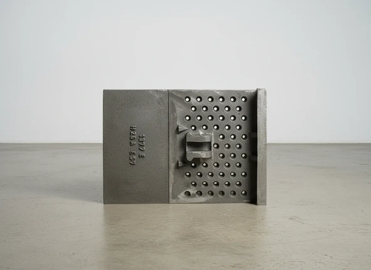
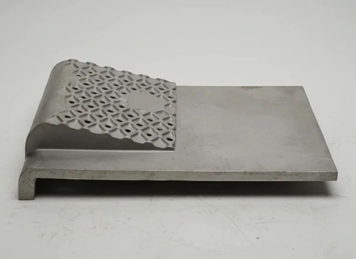
Grate Plates
Precision-cast grate plates with optimised air slot geometry for efficient clinker cooling. Air slot width, taper angle and open area percentage (typically 5–15%) control the volume and distribution of cooling air reaching the clinker bed. Inlet zone plates face clinker at 1,200–1,400°C and require HP40 or HP40Nb alloys; downstream plates use cost-effective HH or HK40 grades. Warp-resistant section design with thermal expansion allowances prevents distortion.
Crossbars & Support Beams
Structural elements supporting grate plate assemblies in reciprocating and walking-floor coolers. Crossbars must maintain grate alignment and proper air distribution while accommodating thermal expansion across the full cooler temperature range. Cast from HK40 or HP40 alloys with precision-machined bearing surfaces that maintain proper grate motion through continuous thermal cycling.
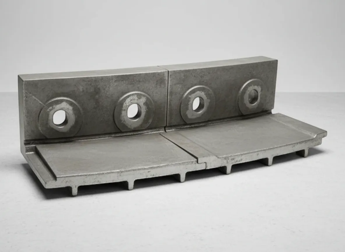
Side Wall Liners
Protective liners for cooler side walls exposed to radiant heat from the clinker bed and abrasion from clinker movement. Segmented designs accommodate thermal expansion without generating restraint stresses. Alloy grade is zoned to match the temperature profile — HP40 at the inlet transitioning to HK40 and HH in cooler downstream zones.
.Df70fKqF_2gfOYX.webp)
Fixed & Movable Frame Castings
Structural castings for reciprocating grate coolers that provide the mechanical framework for grate plate motion. Fixed frames support the stationary grate rows; movable frames reciprocate to transport clinker through the cooler. Precision-machined bearing surfaces and guide features maintain proper grate motion through years of continuous thermal cycling.
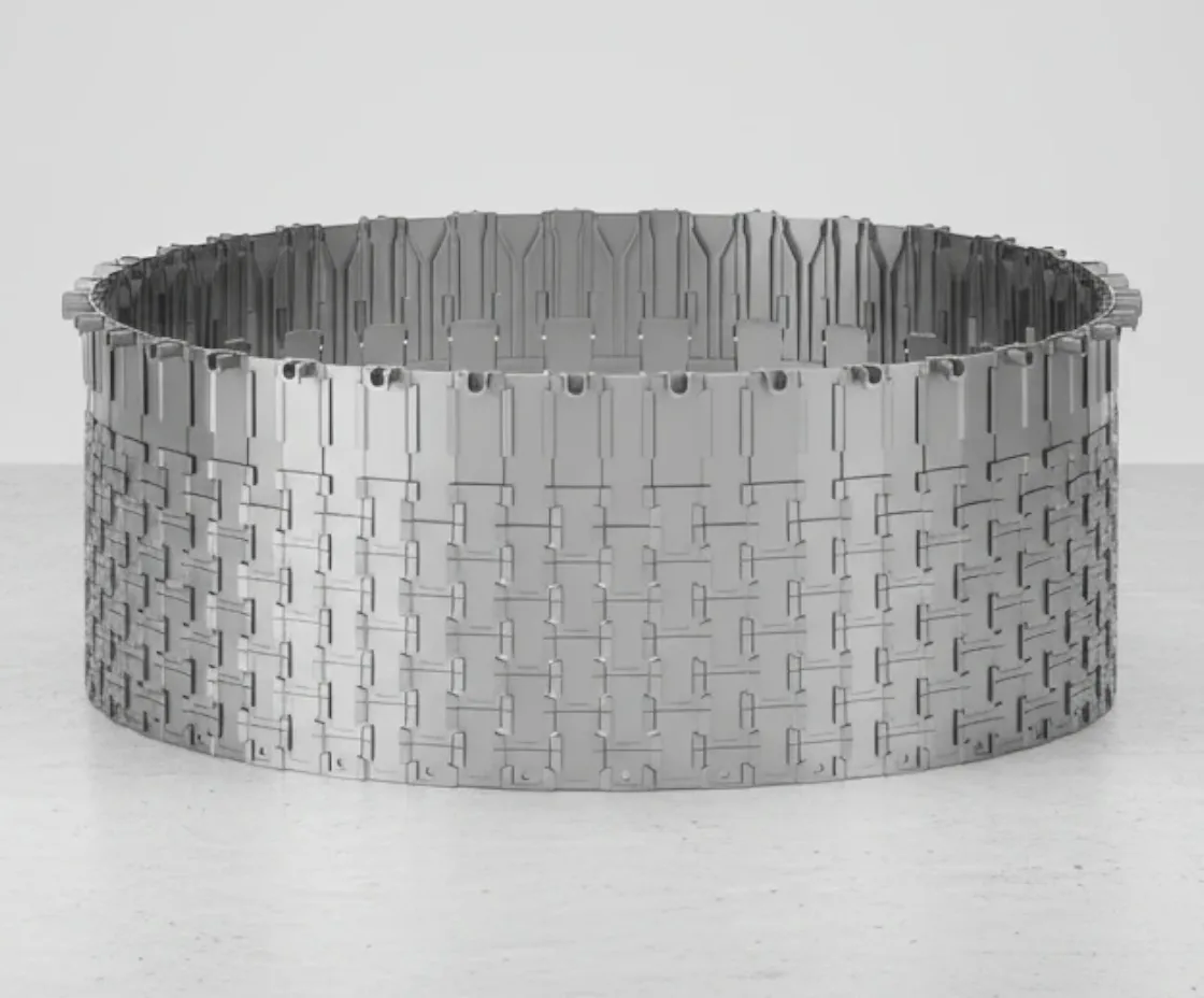
Air Beam Assemblies
Cooling air distribution beams that deliver pressurised air from beneath the grate to the clinker bed above. Modern designs feature replaceable wear caps on the upper surface that can be changed without removing the entire beam assembly. Modular construction allows targeted replacement of worn sections — reducing shutdown time and maintenance cost.
Clinker Breaker Components
Impact-resistant castings for clinker breaker rolls at the cooler discharge. These components fracture oversize clinker lumps to a size suitable for downstream conveying and cement grinding. Heat-resistant alloys handle residual clinker temperature (100–200°C at the cooler discharge) while providing the impact and abrasion resistance needed for continuous clinker size reduction.
Heat-Resistant Alloy Selection for Clinker Coolers
Clinker cooler alloy selection is driven by the extreme temperature gradient from inlet (1,200–1,400°C) to outlet (~100°C). Zone-specific material specification — using premium alloys where the thermal demand justifies it and cost-effective grades elsewhere — optimises total cost of ownership across the full cooler length.
HH Grade (25Cr-12Ni)
ASTM A297 Grade HH (25% Cr, 12% Ni)
Downstream grate plates and components in moderate temperature zones (600–900°C) — cost-effective for positions where the clinker has already been partially cooled
3–5 years (downstream positions)
Limitation: Insufficient oxidation resistance and creep strength above 900°C — will distort and crack in inlet zone positions
HK40 (25Cr-20Ni)
ASTM A297 Grade HK40 (25% Cr, 20% Ni)
Standard grate plates, crossbars and structural components operating at 800–1,100°C — the workhorse alloy for clinker cooler applications
2–3 years (mid-zone positions)
Limitation: Creep strength drops above 1,100°C — not sufficient for inlet zone grate plates directly beneath the kiln discharge
HP40 (25Cr-35Ni)
ASTM A297 Grade HP40 (25% Cr, 35% Ni)
Inlet zone grate plates where clinker arrives at 1,200–1,400°C — superior creep resistance and thermal fatigue life at the highest cooler temperatures
12–18 months (inlet zone)
Limitation: Higher material cost due to increased nickel content — use only where temperature demands justify the premium over HK40
HP40Nb (25Cr-35Ni-Nb)
ASTM A351 Grade HP40Nb (25% Cr, 35% Ni, 1% Nb)
Critical inlet positions with the most extreme thermal stress — niobium carbide precipitation strengthening provides maximum creep rupture life and thermal fatigue resistance
15–24 months (critical inlet zone)
Limitation: Highest cost alloy. Reserved for positions where HP40 does not achieve adequate campaign life due to extreme thermal cycling severity
HW Grade (Ni-Cr-Fe)
ASTM A297 Grade HW (60% Ni, 12% Cr)
Special positions exposed to localised reducing atmospheres — carbon-rich clinker or incomplete combustion zones where carburisation attacks Cr-Ni alloys
Position-specific (carburisation-resistant)
Limitation: Lower oxidation resistance than HK/HP grades in oxidising conditions. Significantly higher cost due to high nickel content — use only where carburisation is a documented failure mechanism
Zone-Specific Alloy Selection Framework
Inlet zone (1,200–1,400°C clinker)? → HP40 or HP40Nb — maximum creep resistance and thermal fatigue life for the hottest positions
Mid-zone (800–1,100°C)? → HK40 — the standard clinker cooler alloy with proven oxidation resistance and adequate creep strength
Downstream zone (300–900°C)? → HH grade — cost-effective with adequate properties for lower-temperature service
Reducing atmosphere pockets? → HW grade (Ni-Cr-Fe) for positions where carburisation attacks standard Cr-Ni alloys
Contact ATF with your cooler model, zone temperature profile and current grate plate performance data — we'll recommend the optimal alloy for each zone to minimise total cost per tonne of clinker cooled.
Compatible Cooler Brands & Models
ATF manufactures clinker cooler components for all major cooler types and suppliers — reciprocating grate, walking-floor and cross-bar designs. Parts are manufactured to OEM specifications or custom-designed for upgraded performance based on operating experience.
FLSmidth
SF Cross-Bar Cooler, Coolax Cooler, ETA Cooler
Including legacy Fuller and F.L.Smidth cooler designs
thyssenkrupp (Polysius)
POLYTRACK Cooler, REPOL Cooler, POLYSIUS Grate Cooler
ThyssenKrupp Industrial Solutions — Polysius cooler technology
KHD Humboldt Wedag
PYROFLOOR Cooler, COMBI-Cooler
Including legacy Humboldt Wedag cooler designs
IKN
Pendulum Cooler, Walking Floor Cooler
IKN GmbH — innovative cooler technology
Claudius Peters
ETA Cooler, Walking Floor Systems
Claudius Peters Technologies — cooler specialists
Others
CBMI/Sinoma, Fives/FCB, Chinese-manufactured coolers
Contact ATF with cooler model and zone specifications for part compatibility
Don't see your cooler model? ATF manufactures replacement components from OEM or customer-supplied drawings for any clinker cooler design. Send your cooler model, zone specifications and grate plate drawings for fit confirmation.
Verify Your CoolerNeed Clinker Cooler Parts?
Provide your cooler model, zone specifications and current grate plate condition. ATF will recommend zone-specific alloys, optimised air slot designs and delivery timing aligned to your annual shutdown.
Clinker Cooler Maintenance Best Practices
Cooler component condition directly affects clinker cooling efficiency, kiln fuel consumption and product quality. Systematic zone-by-zone monitoring allows you to forecast replacement dates accurately and coordinate grate plate orders with your annual shutdown schedule.
Every Shift
- Monitor cooler undergrate air pressures by zone — changes indicate grate plate plugging, damage or clinker bed distribution issues
- Check clinker outlet temperature — rising temperature indicates reduced cooling efficiency from worn or plugged grate plates
- Monitor cooler drive system current and speed — changes indicate grate plate binding, structural damage or clinker flow issues
- Check for red spots on cooler casing — indicates wall liner failure or grate plate burn-through
Weekly
- Review zone-by-zone air flow data and temperature profiles — identify zones with declining cooling performance
- Inspect accessible grate plate surfaces through inspection ports for warping, cracking or air slot plugging
- Check clinker breaker operation — monitor power draw and clinker size at cooler discharge
- Review cooler thermal efficiency calculations — declining heat recovery indicates worn inlet zone components
Monthly
- Inspect air slot condition on accessible grate plates — check for plugging, enlargement from erosion, or deformation
- Check crossbar and frame casting condition — look for cracking, warping or bearing surface wear
- Inspect side wall liners for erosion, cracking or displacement — especially in the inlet zone
- Review clinker breaker hammer condition — check for wear and breakage
Annual Shutdown
- Complete grate plate inspection — measure thickness, check for warping, cracking and air slot condition zone by zone
- Replace inlet zone grate plates that have reached minimum thickness or show thermal fatigue cracking
- Inspect and replace crossbar wear surfaces and frame casting bearing areas as needed
- Replace worn side wall liners — prioritise inlet zone where thermal and abrasive conditions are most severe
- Inspect and refurbish air beam assemblies — replace worn caps and check air seal integrity
- Document all measurements for trend analysis — forecast zone-specific replacement dates for next shutdown planning
Clinker Cooler Zone Specifications
| Zone | Clinker Temp | Alloy | Grate Life |
|---|---|---|---|
| Inlet (Zone 1) | 1,200–1,400°C | HP40 / HP40Nb | 12–18 months |
| Hot Mid (Zone 2) | 900–1,200°C | HK40 / HP40 | 18–30 months |
| Cool Mid (Zone 3) | 600–900°C | HK40 / HH | 2–3 years |
| Discharge (Zone 4) | 100–600°C | HH | 3–5 years |
Temperatures and alloy recommendations are indicative. Actual zone boundaries depend on cooler design, clinker production rate, air flow distribution and raw material characteristics. Contact ATF with your cooler temperature profile for zone-specific recommendations.
Common Clinker Cooler Problems & Solutions
Cooler performance issues directly affect kiln fuel consumption, clinker quality and plant throughput. Identifying grate plate and component degradation early allows planned corrective action rather than emergency shutdown.
Grate Plate Warping or Distortion
Probable Causes
- Thermal gradient across plate thickness — hot clinker surface expands more than air-cooled underside
- Mounting hardware or adjacent plates restraining free thermal expansion — generating internal stresses above yield strength
- Incorrect alloy for the position temperature — HH or HK40 used where HP40 is required
- Insufficient section thickness — thin sections develop higher thermal gradients than designed thicker sections
Corrective Actions
- Review grate plate section design — ATF designs use controlled thicknesses that promote even heat distribution
- Check mounting configuration — ensure clearance slots and expansion joints are not restricted by clinker buildup
- Review alloy selection per cooler zone — upgrade to HP40 or HP40Nb in zones where distortion is recurring
- Consider air slot pattern modification to reduce thermal gradient across the plate cross-section
Rising Clinker Outlet Temperature
Probable Causes
- Grate plate air slots plugged with fine clinker dust — reducing cooling air volume through the clinker bed
- Worn grate plates with enlarged air slots — air bypasses through enlarged slots instead of distributing through the bed
- Clinker bed depth inconsistency — too thin in some zones allowing air to blow through without cooling clinker
- Inlet zone grate plates distorted or cracked — reducing cooling effectiveness in the highest-temperature zone
Corrective Actions
- Inspect grate plates for plugged air slots — clean or replace plates with chronic plugging issues
- Replace grate plates with enlarged air slots — worn slots reduce cooling efficiency even if the plate is not visually damaged
- Review clinker distribution across the cooler width — adjust cooler speed or bed depth control
- Prioritise inlet zone grate plate replacement — this zone has the greatest impact on overall cooling efficiency
Grate Plate Cracking or Breakage
Probable Causes
- Thermal fatigue from continuous cycling — especially in inlet zone where temperature differential exceeds 1,000°C
- Mechanical restraint preventing thermal expansion — generating stresses that exceed alloy strength at temperature
- Reducing atmosphere pockets from carbon-rich clinker attacking the Cr-Ni alloy grain boundaries
- Casting defects (porosity, inclusions) creating stress concentrations that initiate cracks during thermal cycling
Corrective Actions
- Review alloy selection — upgrade to HP40Nb for inlet positions where HP40 is cracking from thermal fatigue
- Inspect mounting and expansion allowances — ensure grate plates can expand freely without restraint
- For reducing atmosphere issues, consider HW grade (Ni-Cr-Fe) for affected positions
- Specify NDT (radiographic or ultrasonic) on replacement castings to reject plates with internal defects
Uneven Clinker Cooling Across Cooler Width
Probable Causes
- Side wall liner failure exposing one side to greater heat loss — creating asymmetric clinker bed temperature
- Grate plates in different condition across the width — some zones cooled effectively, others not
- Air distribution imbalance between cooler zones — fan damper settings or ducting issues
- Clinker distribution from kiln not centred — clinker bed deeper on one side of the cooler
Corrective Actions
- Inspect side wall liners across the full cooler length — replace any that are missing, cracked or displaced
- Map grate plate condition across the cooler width — replace plates that are in significantly worse condition than their neighbours
- Check and balance undergrate air pressures across all zones — verify fan and damper operation
- Review kiln discharge arrangement and nose ring condition — ensure clinker falls centrally into the cooler
Excessive Cooler Drive Load / Mechanical Binding
Probable Causes
- Warped grate plates interfering with reciprocating motion — distorted plates jam against adjacent rows
- Clinker buildup between fixed and movable grate rows — restricting movement
- Frame casting bearing surfaces worn — increasing friction and misalignment of grate motion
- Crossbar distortion changing grate plate alignment — creating interference during reciprocation
Corrective Actions
- Inspect grate plates for warping that could cause interference — replace distorted plates
- Clean clinker buildup from between grate rows and in mechanical clearance areas
- Inspect frame casting bearing surfaces — machine or replace if worn beyond tolerance
- Check crossbar alignment and condition — replace any showing thermal distortion or cracking
Frequently Asked Questions
Answers to common questions about clinker cooler grate plates, alloy selection, air slot design, maintenance and ordering. Can't find what you're looking for?
Contact Our TeamWhat causes grate plate warping and how do ATF designs prevent it?
How does grate plate design affect clinker cooling efficiency?
What is the typical service life of clinker cooler grate plates?
What information does ATF need to quote clinker cooler parts?
Can ATF supply grate plates with upgraded air slot designs?
Are ATF clinker cooler parts compatible with OEM equipment?
What is the difference between HH, HK40, HP40 and HP40Nb for cooler parts?
What is the typical lead time for clinker cooler parts?
Optimize Cooler Performance
Heat-resistant grate plates engineered for predictable service life and efficient clinker cooling. ATF provides zone-specific alloy recommendations, optimised air slot designs and full material certification.
Contact ATF EngineeringSolicite una Cotización Gratuita Hoy
Nuestro equipo de ingeniería responde en 24 horas con especificaciones detalladas, recomendaciones de materiales y precios competitivos.