

Pièces pour Broyeur Vertical à Rouleaux
Pièces de VRM | Galets et tables de broyage | ATF
Pièces de VRM : galets et segments de table en fonte au chrome, Ni-Hard et alliages avec rechargement dur.
Vertical Roller Mill Parts
Vertical roller mills grind raw materials by pressing hydraulically loaded rollers against a rotating grinding table. The feed — typically limestone, clay, slag, clinker or coal — is crushed between the roller and table surfaces under pressures exceeding 50 MPa. This high-stress compression grinding progressively wears both surfaces, changing the roller-to-table gap and reducing grinding efficiency. VRMs are the dominant grinding technology in modern cement plants and are increasingly used in mineral processing, power generation and industrial minerals applications.
VRM wear parts operate under fundamentally different conditions from crusher liners or mill liners. Where crusher parts rely on impact-driven work-hardening of manganese steel, and ball/SAG mill liners absorb cataracting impact, VRM components must resist sustained compressive abrasion at elevated temperatures. The dominant material families — high-chrome white iron, Ni-Hard and chromium carbide overlay (CCO) hardfacing — are chosen for their carbide volume fraction rather than toughness. ATF manufactures the complete range of VRM grinding rollers, table segments and auxiliary parts to OEM specifications for all major mill brands.
ATF VRM grinding roller and table segments — the contact zone between roller and table is where material selection determines grinding efficiency and wear life.
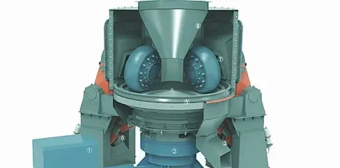
How a Vertical Roller Mill Works
In a VRM, raw material is fed onto the centre of a rotating grinding table. Centrifugal force moves the material outward beneath hydraulically loaded grinding rollers. Each roller compresses the material against the table surface, fracturing it by compression and shear. Hot gas enters through the louvre ring surrounding the table, drying the material and carrying fine particles upward to the separator. Coarse particles rejected by the separator fall back onto the table for re-grinding.
Feed & Bed Formation
Raw material enters through the feed chute onto the centre of the rotating grinding table. Centrifugal force from table rotation (typically 25–35 RPM depending on table diameter) moves the material outward toward the grinding track — the annular zone where rollers contact the table. A dam ring at the table edge retains material to maintain the grinding bed depth (typically 30–80 mm). Bed depth control is critical — too thin and metal-to-metal contact damages components; too thick and grinding pressure is insufficient.
Compression Grinding
Two, three or four hydraulically loaded rollers press down on the material bed with forces that create contact pressures exceeding 50 MPa. Material particles are fractured by compression between the roller surface and the table segment — not by impact as in crushers or tumbling mills. This energy-efficient comminution mechanism makes VRMs 30–40% more energy-efficient than ball mills for the same product fineness. The roller and table profiles must remain within tolerance to maintain even pressure distribution across the grinding track.
Classification & Product Discharge
Hot gas enters through the louvre ring (nozzle ring) surrounding the grinding table at controlled velocity. The gas stream dries the ground material and carries fine particles upward to the separator mounted above the grinding zone. The separator (static, dynamic or hybrid) classifies particles by size — product-fineness material passes through to collection, while coarse rejects fall back onto the grinding table for another pass under the rollers. Separator rotor speed and guide vane position control the product fineness cut point.
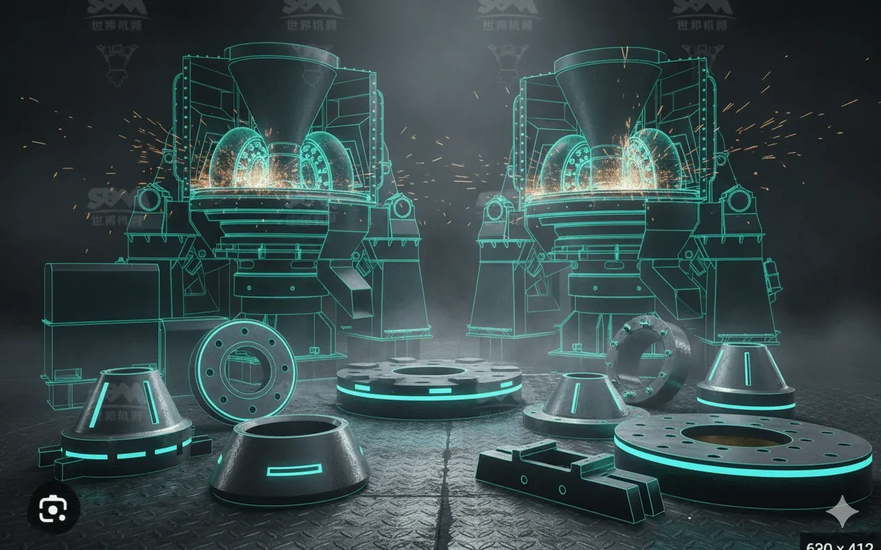
VRM Grinding Components & Wear Parts
A vertical roller mill requires three main categories of wear components. Each component page provides detailed material options, rebuild vs replace guidance and OEM compatibility information.
Grinding Rollers
The primary wear component in any VRM. Hydraulically loaded rollers compress raw material against the grinding table under pressures exceeding 50 MPa. Progressive wear creates a concave profile that reduces grinding pressure distribution, increases specific energy consumption and reduces product fineness. Available as solid high-chrome castings, Ni-Hard castings, segmented designs, or hardfaced rebuilds with chromium carbide overlay (CCO).
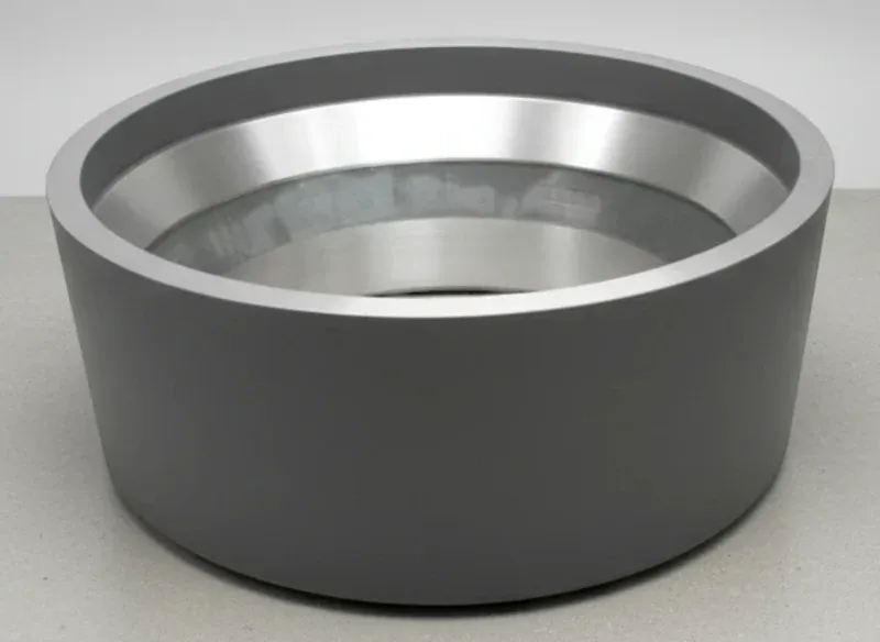
Grinding Table Segments
The stationary grinding surface against which rollers compress the material bed. Table segments wear into a groove pattern matching the roller contact path — when worn beyond tolerance, the roller-to-table gap cannot maintain target bed depth and product fineness drops. Table segments are typically cast in high-chrome white iron or Ni-Hard, with hardfaced overlay options for rebuild.
Additional VRM Parts
Louvre rings (nozzle rings) control hot gas entry velocity and distribution around the grinding table. Dam rings set the material bed depth. Separator components (guide vanes, rotor blades) determine product fineness cut point. Armour plates, housing wear plates and feed chute liners protect structural components from abrasive material flow.
Material Selection for VRM Wear Parts
VRM components operate under high-stress compressive abrasion with minimal impact. Material selection prioritises hardness and carbide volume fraction over toughness — the opposite of crusher liners. The choice between alloy families depends on raw material abrasiveness, operating temperature, whether the part will be rebuilt or replaced, and the economics of cost per tonne ground.
High-Chrome White Iron (Cr15–Cr28)
15–28% Cr white iron (58–64 HRC)
Solid-cast grinding rollers and table segments — the highest carbide volume fraction for maximum abrasion resistance under sustained compressive grinding
Longest (baseline for VRM applications)
Limitation: Brittle under impact — VRM operating conditions are compressive, not impact-driven, making this acceptable. However, tramp metal in feed or roller drop events can crack castings
Ni-Hard 4 (Ni-Cr White Iron)
Ni-Cr white iron (54–58 HRC)
Grinding rollers and table segments where slightly better thermal stability is needed — coal mills, slag grinding, or applications with temperature cycling
0.7–0.9× high-chrome in abrasive conditions, but better thermal shock resistance
Limitation: Lower hardness than high-chrome white iron — shorter wear life in highly abrasive applications like raw meal grinding
CCO Hardfacing (Chromium Carbide Overlay)
Cr₇C₃ carbide overlay (58–65 HRC)
Cost-effective roller rebuilds and table segment resurfacing — restores the grinding profile without replacing the entire casting. Field-applicable with adjustable overlay thickness
0.6–0.8× solid high-chrome per campaign, but at 30–50% of replacement cost
Limitation: Overlay adhesion depends on base metal condition and surface preparation. Multiple rebuild cycles thin the base casting — limited by minimum safe wall thickness
Ceramic-Metal Composite (CMC)
Alumina or zirconia ceramic tiles in metallic matrix
Extremely abrasive applications (slag grinding, high-silica raw meal) where conventional alloys wear too quickly — ceramic tiles provide hardness that metallic alloys cannot match
2–4× high-chrome in extreme abrasion conditions
Limitation: Highest cost option. Ceramic tiles can crack under thermal shock or tramp metal impact. Limited to applications where the extreme abrasion justifies the premium
VRM Material Selection Framework
Raw meal grinding (limestone, clay)? → High-chrome white iron (Cr20–Cr28) for maximum abrasion resistance at moderate temperatures
Coal or petcoke grinding? → Ni-Hard 4 for better thermal stability and explosion-resistant grinding conditions
Cement or slag finish grinding? → High-chrome or CCO overlay — depends on clinker abrasiveness and whether new or rebuild
Roller rebuild (base casting sound)? → CCO hardfacing at 30–50% of new casting cost — the standard choice for planned roller rebuilds
Contact ATF with your mill model, raw material type, abrasion index, operating temperature and current wear life — we'll recommend the optimal material and whether to rebuild or replace.
Compatible VRM Brands & Models
ATF manufactures replacement grinding rollers, table segments and auxiliary parts for all major vertical roller mill brands. Parts are manufactured to OEM dimensional tolerances from OEM or customer-supplied drawings. Send your mill model, drawing references and current wear data for dimensional confirmation and material recommendation.
Loesche
LM 28.4, LM 35.4, LM 46.4, LM 53.3+3, LM 56.3+3, LM 69.6
Conical rollers — Master + Slave configuration on larger models
FLSmidth (ATOX)
ATOX 32.5, ATOX 37.5, ATOX 42.5, ATOX 47.5, ATOX 52.5, ATOX 57.5
Cylindrical rollers with spherical roller ends
Gebr. Pfeiffer (MPS)
MPS 3070, MPS 3350, MPS 4000, MPS 4750, MPS 5000, MPS 5300, MPS 5600
Conical rollers with individual hydraulic loading
Polysius / ThyssenKrupp
Quadropol QM series — various table diameters
Four-roller design — roller type varies by generation
UBE / IHI
UBE vertical mills — various models for raw meal, cement and coal
Tire-type rollers — common in Asian cement plants
Others
Claudius Peters, Raymond, Williams, Chinese-manufactured VRMs
Contact ATF with mill model and drawing references for fit confirmation
Don't see your VRM manufacturer? ATF manufactures VRM parts from customer-supplied or OEM drawings for any vertical roller mill. Send your mill model, drawing references and current wear measurements for fit confirmation and material recommendation.
Send Mill Model for Parts CompatibilityPlanning a VRM Shutdown?
Send your mill specifications, current roller/table profile measurements and shutdown schedule. ATF will recommend whether to rebuild or replace, confirm material selection and coordinate delivery to your maintenance window.
VRM Wear Part Maintenance Best Practices
VRM roller and table wear directly affects product fineness, mill throughput and specific energy consumption. Regular profile measurement and condition monitoring allow you to forecast replacement dates accurately, schedule rebuilds at the optimal time, and avoid unplanned shutdowns that disrupt production.
Every Shift
- Monitor mill power draw and vibration — sudden changes indicate material bed instability, roller wear or tramp metal
- Check hydraulic system pressure on grinding rollers — pressure drop indicates a hydraulic leak or accumulator fault
- Monitor mill outlet temperature and differential pressure across the separator — changes indicate process drift
- Listen for abnormal grinding sounds — metallic contact between roller and table means bed depth is too low
Weekly
- Sample and analyse product fineness (Blaine value or particle size) — deviation indicates roller or table wear
- Inspect louvre ring / nozzle ring segments for wear or material build-up restricting gas flow
- Check dam ring height — worn dam rings reduce bed depth and grinding efficiency
- Review separator reject rate — increasing rejects may indicate worn rollers producing coarser particles
Monthly
- Measure roller profile using laser profiling or template gauges — map the wear pattern and compare to OEM profile
- Inspect table segment surface condition — check for uneven wear grooves, cracking or material build-up
- Check roller pivot and bearing condition — worn bearings allow roller misalignment and uneven grinding
- Inspect armour plates, feed chute liners and housing wear plates for wear-through or erosion
At Shutdown / Roller Change
- Measure remaining roller and table segment material thickness at multiple points
- Assess whether roller rebuild (CCO hardfacing) is viable or full replacement is needed — check base casting integrity
- Inspect and replace louvre ring segments, dam ring plates and separator wear parts as needed
- Check roller shaft, bearing housings and hydraulic cylinder condition — replace seals and worn components
- Verify roller-to-table gap and grinding geometry after installing new or rebuilt components
Typical VRM Operating Parameters by Application
| Parameter | Raw Meal | Cement Finish | Coal / Petcoke |
|---|---|---|---|
| Feed Size | Up to 100 mm | Up to 40 mm | Up to 50 mm |
| Product Fineness | 10–15% R90µm | 3,200–5,000 Blaine | 5–15% R90µm |
| Grinding Pressure | 40–60 kN/m² | 60–90 kN/m² | 30–50 kN/m² |
| Operating Temp | 80–120°C | 90–130°C | 60–90°C |
| Roller Material | Hi-Chrome / CCO | Hi-Chrome / CCO | Ni-Hard / CCO |
| Typical Roller Life | 6,000–12,000 hrs | 4,000–8,000 hrs | 8,000–15,000 hrs |
Parameters are indicative. Actual values depend on mill model, raw material properties, moisture content and product specification. Contact ATF for material recommendations specific to your operating conditions.
Common VRM Problems & Solutions
VRM operational issues often trace back to wear component condition. Recognising the relationship between roller/table wear and process performance allows you to schedule rebuilds or replacements proactively — before product quality or throughput is significantly affected.
Reduced Product Fineness / Higher Residue
Probable Causes
- Roller profile worn concave — reduced contact area decreases grinding pressure on the material bed
- Table segment groove worn beyond tolerance — roller-to-table gap too large for effective compression
- Separator rotor or guide vanes worn — coarser particles passing to product instead of being rejected
- Dam ring height too low — insufficient bed depth for effective grinding under roller pressure
Corrective Actions
- Measure roller profile against OEM specification — rebuild or replace if worn beyond tolerance
- Inspect table segments for groove depth and surface condition — replace if worn beyond minimum thickness
- Check separator rotor blade and guide vane condition — replace worn components to restore classification
- Measure dam ring height — restore to design height or adjust for current feed conditions
Excessive Mill Vibration
Probable Causes
- Material bed instability — insufficient feed, moisture variation or tramp metal destabilising the grinding bed
- Uneven roller wear creating asymmetric grinding forces — one roller worn more than the others
- Roller bearing failure or excessive clearance allowing roller to oscillate during grinding
- Louvre ring damage causing uneven gas distribution and localised bed blow-through
Corrective Actions
- Check feed rate stability, moisture content and whether tramp metal protection is functioning correctly
- Compare roller profiles across all rollers — replace or rebuild the most worn roller first to restore balance
- Inspect roller bearings for play, temperature and lubrication condition — replace bearings showing wear
- Inspect louvre ring for damaged or missing segments — replace to restore even gas distribution
Higher Specific Energy Consumption (kWh/t)
Probable Causes
- Worn roller profile reducing effective grinding pressure — mill draws more power for less output
- Table segment wear reducing effective compression geometry — energy wasted in material recirculation
- Internal recirculation rate too high due to worn separator or incorrect settings
- Insufficient bed depth from worn dam rings — rollers partially grinding on metal instead of material
Corrective Actions
- Measure roller and table profiles — rebuild or replace components worn beyond efficient grinding geometry
- Review separator settings and reject rate — adjust rotor speed or replace worn blades
- Restore dam ring height and check feed rate to maintain optimal bed depth
- Compare current kWh/t against baseline after new component installation — track degradation over time
Roller or Table Segment Cracking
Probable Causes
- Tramp metal in feed — uncrushable objects create point-load stress that exceeds casting strength
- Thermal shock from rapid temperature changes — startup/shutdown cycling stresses brittle high-chrome castings
- Defective casting with internal porosity or inclusions — stress concentrations initiate cracks during operation
Corrective Actions
- Review and improve tramp metal detection and removal systems upstream of the VRM
- Implement gradual temperature ramp-up and ramp-down procedures to reduce thermal stress on castings
- Inspect new castings with ultrasonic or magnetic particle testing before installation — reject defective parts
- For recurring cracking, consider switching to Ni-Hard (better thermal shock resistance) or CCO overlay on a tougher base casting
Reduced Mill Throughput
Probable Causes
- Worn rollers and table segments requiring more grinding passes — material circulates internally instead of reaching product fineness
- Louvre ring partially blocked — reduced gas velocity cannot transport fine material to separator
- Separator inefficiency — worn guide vanes or rotor blades sending product-size material back for re-grinding
Corrective Actions
- Measure roller and table condition — schedule rebuild or replacement to restore grinding efficiency
- Clean and inspect all louvre ring segments — replace any that are worn, bent or partially blocked
- Inspect separator internals during next shutdown — replace worn guide vanes and rotor blades
Frequently Asked Questions
Answers to common questions about VRM grinding rollers, table segments, material selection, rebuild options and ordering. Can't find what you're looking for?
Contact Our TeamWhat is the difference between a VRM roller rebuild and replacement?
How do I know when to replace VRM rollers and table segments?
What information does ATF need to quote VRM parts?
Can ATF supply rollers for any VRM manufacturer?
What is the difference between high-chrome white iron and Ni-Hard for VRM parts?
How does CCO hardfacing compare to solid high-chrome castings?
What causes uneven wear on VRM rollers?
What is the typical lead time for VRM parts?
Request a VRM Parts Quote
Send your mill model, drawing references and current wear measurements. ATF will confirm dimensional fit, recommend materials (new casting vs rebuild) and provide delivery timing aligned to your shutdown schedule.
Get VRM QuoteDemandez un Devis Gratuit Aujourd'hui
Notre équipe d'ingénierie répond sous 24 heures avec des spécifications détaillées, des recommandations de matériaux et des prix compétitifs.