

Pièces pour Cimenterie
Pièces de préchauffeur | Pièces pour cimenterie | ATF
Pièces d'usure pour préchauffeurs de cimenteries : blindages de cyclone, tubes plongeants et déflecteurs. Alliages résistants à la chaleur 800-1000 C.
Preheater Wear Parts for Cement Plant Cyclone Systems
Cement preheater systems operate at temperatures between 800 and 1,000°C where raw meal is progressively heated by counter-flowing kiln exhaust gases across four to six cyclone stages before entering the rotary kiln for calcination and clinkerisation. Cyclone liners, dip tubes, splash plates and riser duct liners in these systems face a severe combination of continuous thermal cycling, erosive high-velocity particle flows carrying raw meal at 15–30 m/s, and chemical attack from alkali sulfates and chlorides that condense on component surfaces.
Component failure forces unplanned shutdowns costing cement plants USD 20,000–50,000 per day in lost production plus expensive refractory repair. ATF preheater parts are manufactured from ASTM A297 and ASTM A351 heat-resistant casting alloys — HK40 (25Cr-20Ni), HP40 (25Cr-35Ni) and HP40Nb — each selected for the specific temperature, erosion intensity and chemical environment at its installed position. All components are designed with controlled section thicknesses and thermal expansion allowances to support 330+ days/year uptime.
.Df70fKqF_2gfOYX.webp)
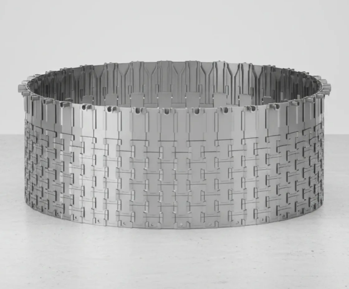
ATF preheater parts — cyclone liners, dip tubes and splash plates cast in HK40 and HP40 heat-resistant alloys, engineered for 800–1,000°C continuous service in cement plant cyclone systems.
How Cement Preheater Cyclone Systems Work
Understanding the thermal, erosive and chemical conditions inside each cyclone stage explains why position-specific alloy selection, controlled section thicknesses and thermal expansion design are critical to achieving the 330+ days/year uptime that modern cement plant economics demand.
Raw Meal Feed & Gas Counter-Flow
Raw meal (ground limestone, clay, sand and iron ore) is fed into the top of the preheater tower and flows downward through 4–6 cyclone stages by gravity. Simultaneously, hot exhaust gas from the rotary kiln (800–1,100°C) flows upward through the riser ducts and cyclones in counter-current to the raw meal. This counter-flow arrangement maximises heat transfer — the raw meal is progressively heated from ambient to ~850°C before entering the kiln, recovering ~50% of the kiln's thermal energy.
Cyclone Separation & Wear
In each cyclone stage, the gas-meal mixture enters tangentially and spirals around the cyclone body. Centrifugal force separates the heavier raw meal particles from the gas stream — the meal drops through the dip tube to the next stage while the cleaned gas rises through the vortex finder. Raw meal particles at 15–30 m/s continuously erode the cyclone liner walls, dip tube bore and splash plate impact zones. The erosion pattern is specific to each cyclone geometry and operating condition.
Calcination & Chemical Attack
In the lowest stages and calciner zone (900–1,000°C), raw meal begins to calcine (release CO₂ from limestone). At these temperatures, alkali sulfates (K₂SO₄, Na₂SO₄) and chlorides from the raw materials volatilise in the kiln, rise with the exhaust gas, and condense on cooler component surfaces in the preheater — particularly in the 700–900°C condensation zone. This alkali cycle creates a chemical attack that penetrates grain boundaries and accelerates alloy degradation alongside the mechanical erosion.
Preheater Wear Components
ATF manufactures the complete range of preheater wear parts for cyclone stages 1–6, riser ducts and meal distribution systems. Each component type requires specific alloy selection, section thickness and thermal expansion design for its operating position.
Cyclone Liners
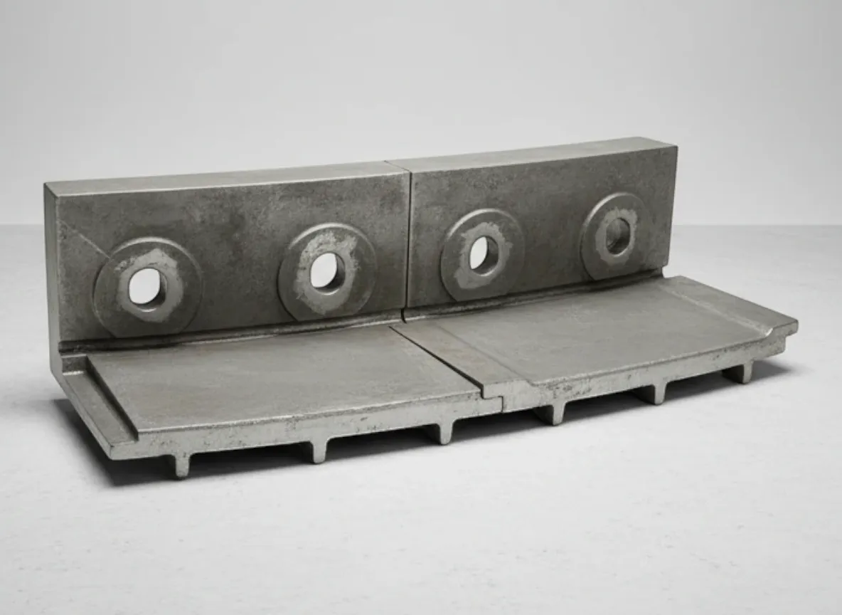
Segmented liner systems protecting the interior walls of cyclone stages 1–6. Each stage operates at a different temperature and particle velocity — requiring position-specific alloy selection. Upper stages (3–6) use HK40 alloy for oxidation resistance at 800–950°C; lower stages use HP40 or HP40Nb for superior creep strength approaching 1,000°C. Liner thickness and profile are optimised for the erosion pattern specific to each cyclone geometry.
Dip Tubes
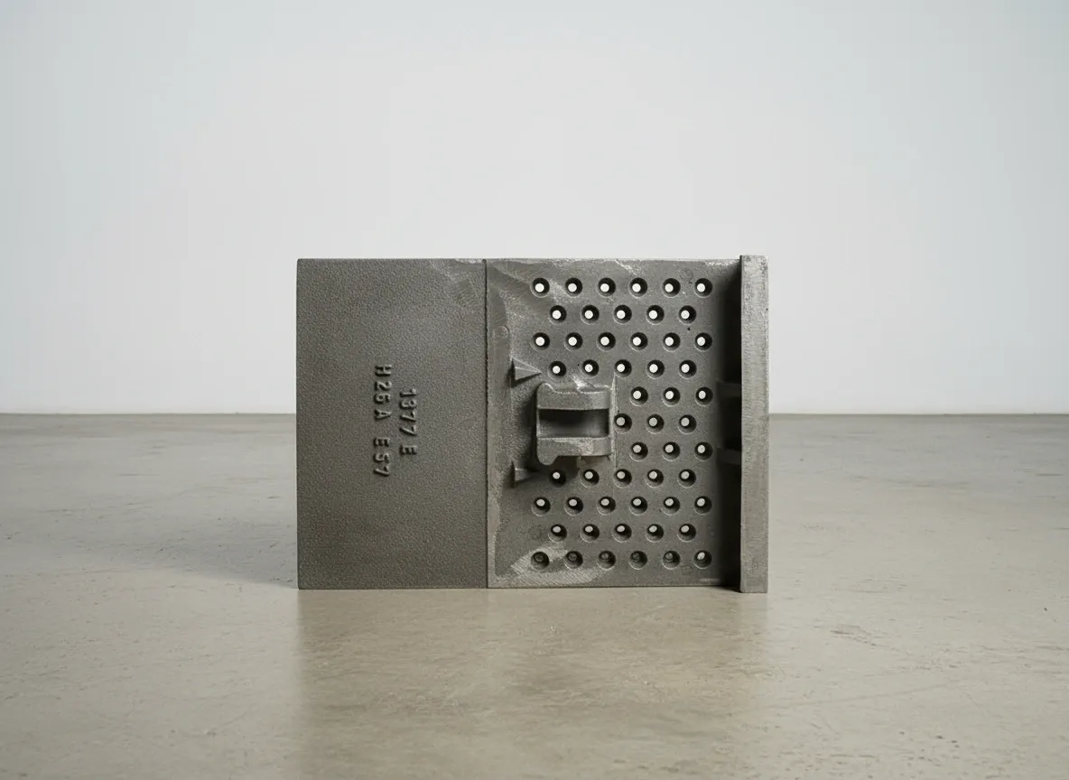
Precision-cast dip tubes (vortex finders) for cyclone meal discharge. These critical components direct the raw meal flow from each cyclone stage to the next while maintaining separation efficiency. Dip tubes experience concentrated erosion at the inner bore entrance and lower cone section where particle velocity is highest. High-chrome cast iron tips (28% Cr, 550–650 HB) are used at erosion-critical zones.
Splash Plates
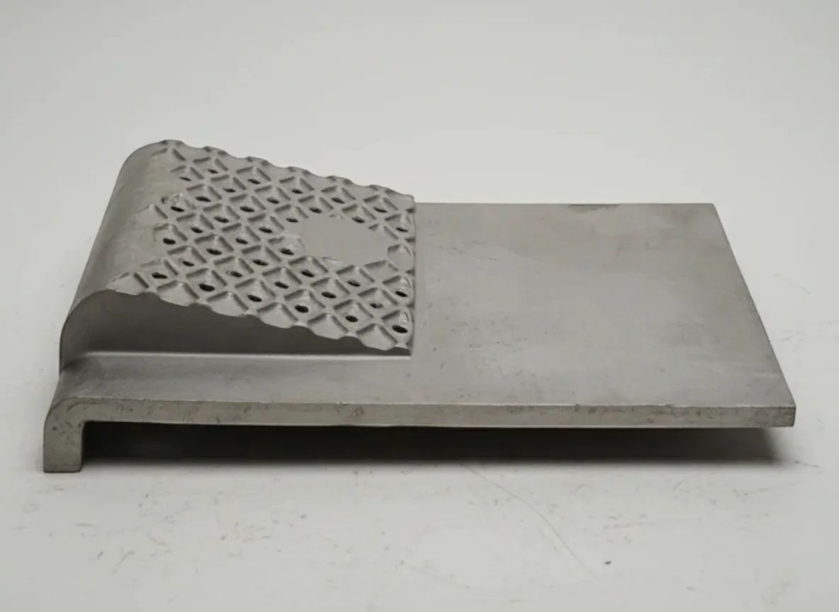
Protective plates installed at high-wear impact zones where raw meal enters and impacts cyclone walls. Thickened sections at impact points extend service intervals between shutdowns. Splash plates absorb the kinetic energy of high-velocity particle streams (15–30 m/s) that would otherwise erode the cyclone shell directly — converting an expensive shell repair into a routine plate replacement.
Riser Duct Liners
Abrasion-resistant liner segments for the gas riser ducts connecting cyclone stages. Riser ducts carry hot exhaust gas (laden with raw meal particles) upward between cyclone stages. Liner segments are designed for bolt-in replacement without major refractory work — minimising shutdown duration. Alloy grade is matched to the temperature and erosion intensity at each duct position.
Meal Chutes & Auxiliary Parts
Wear-resistant chute liners, deflector plates, expansion joints and ancillary components for raw meal distribution systems. Engineered profiles optimise material flow while minimising erosion. Also includes calciner inlet components, flap valve housings and other structural wear parts operating in the 800–1,000°C temperature range.
Heat-Resistant Alloy Selection for Preheater Parts
Preheater component alloy selection is driven by operating temperature and chemical environment at each cyclone stage. Lower stages (closest to the kiln) experience the highest temperatures and require premium HP-grade alloys. Upper stages operate at lower temperatures where HK40 provides adequate performance at lower cost. Using the wrong grade in the wrong position leads to either premature failure or unnecessary material expense.
HK40 (25Cr-20Ni)
ASTM A297 Grade HK40 (25% Cr, 20% Ni)
Standard alloy for upper cyclone stages (3–6) and riser ducts operating at 800–950°C — excellent oxidation resistance with adequate creep strength for moderate-temperature service
12–24 months typical (position-dependent)
Limitation: Creep rupture strength drops significantly above 950°C — not suitable for lower cyclone stages or calciner zones without upgrading to HP grade
HP40 (25Cr-35Ni)
ASTM A297 Grade HP40 (25% Cr, 35% Ni)
Lower cyclone stages and calciner zones exceeding 950°C — the higher nickel content provides superior creep resistance and thermal fatigue life at elevated temperatures
18–36 months typical in lower cyclone stages
Limitation: Higher material cost than HK40 due to increased nickel content — use only where temperature demands justify the premium
HP40Nb (25Cr-35Ni-Nb)
ASTM A351 Grade HP40Nb (25% Cr, 35% Ni, 1% Nb)
The highest temperature zones approaching 1,000°C — niobium carbide precipitation strengthening provides the best creep rupture life at extreme temperatures
24–36 months in hottest positions
Limitation: Highest cost heat-resistant alloy. Niobium additions require precise heat treatment control — under-aged or over-aged microstructure reduces high-temperature strength
High-Cr Cast Iron (28% Cr)
28% Cr white iron (550–650 HB)
Dip tube tips, splash plate impact zones and localised high-velocity erosion areas where maximum erosion resistance is critical — but only where temperature conditions permit (below ~600°C)
Sacrificial inserts replaced at each major shutdown
Limitation: Cannot withstand continuous service above ~600°C — limited to specific erosion-critical zones where local temperature is lower than the surrounding gas stream
Stage-by-Stage Alloy Selection Framework
Upper stages 4–6 (800–900°C)? → HK40 (25Cr-20Ni) — proven oxidation resistance, lowest material cost
Mid stages 2–3 (900–950°C)? → HP40 (25Cr-35Ni) — higher Ni for improved creep resistance at elevated temperature
Lowest stage 1 and calciner zone (950–1,000°C)? → HP40Nb — niobium strengthening for maximum creep rupture life
Dip tube tips and erosion-critical zones? → High-Cr cast iron inserts (28% Cr) where temperature permits (<600°C)
Alloy recommendations assume stable oxidising atmosphere. Abnormal conditions (reducing atmosphere, alkali buildup, co-processing alternative fuels) may require upgraded materials. Contact ATF with your kiln line specifications and operating data.
Compatible Cement Equipment Brands
ATF manufactures preheater components compatible with all major cement equipment suppliers. Parts are reverse-engineered to OEM specifications or custom-designed for upgraded performance. All components supplied with full material certification to ASTM A297/A351 and dimensional reports per approved drawings.
FLSmidth
ILC Series Preheaters, SLC Calciners, Cross-Bar Cooler kiln lines
Including legacy Fuller and F.L.Smidth designs
thyssenkrupp (Polysius)
DOPOL Preheaters, PREPOL Calciners, POLCID Systems
ThyssenKrupp Industrial Solutions — Polysius cement technology
KHD Humboldt Wedag
PYROCLON Calciners, Cyclone Preheater Systems
Including legacy Humboldt Wedag and KHD designs
Loesche
Preheater Tower Internals, Calciner Components
Loesche preheater and calciner systems
CBMI / Sinoma
TDF Calciners, Cyclone Preheater Lines, complete kiln systems
CBMI Construction — Sinoma International cement technology
Others
Gebr. Pfeiffer, IKN, Fives FCB, Claudius Peters, Chinese-manufactured systems
Contact ATF with your preheater tower specifications for fit confirmation
Don't see your preheater system? ATF manufactures replacement components from customer-supplied or OEM drawings for any cement preheater tower. Send your kiln line specifications, cyclone drawings and current component condition for fit confirmation and alloy recommendation.
Verify Your Preheater SystemNeed Preheater Parts for Your Cement Plant?
Provide your kiln line specifications, cyclone dimensions and current component condition. ATF will recommend the correct alloy grade for each position and provide delivery timing aligned to your annual shutdown schedule.
Preheater Component Maintenance Best Practices
Preheater component failures cause unplanned shutdowns costing USD 20,000–50,000 per day in lost production. Systematic condition monitoring, thickness trending and planned replacement during annual shutdowns maximise component life while avoiding the catastrophic cost of an unplanned stop.
Every Shift
- Monitor cyclone stage temperatures and pressure drops — sudden changes indicate material buildup, liner failure or bypass
- Check preheater tower skin temperatures using IR scanning — hot spots indicate liner wear-through or refractory loss
- Monitor kiln exhaust gas composition — reducing atmosphere from incomplete combustion accelerates alloy degradation
- Record differential pressure across each cyclone stage — increasing ΔP indicates buildup or blockage
Weekly
- Review cyclone efficiency data (separation rate) — declining efficiency may indicate dip tube wear or liner damage
- Check inspection port conditions for evidence of material buildup, coating spalling or liner erosion
- Monitor meal distribution to each cyclone stage — uneven flow causes localised overheating and accelerated wear
- Review alkali and chloride bypass system operation — bypass failures increase chemical attack on preheater components
Monthly / During Minor Stops
- Visual inspection of accessible cyclone internals through inspection ports — look for liner cracking, spalling or erosion
- Measure cyclone liner thickness at known high-wear points using ultrasonic gauges where accessible
- Inspect splash plate condition at material entry points — these are the first components to show erosion
- Check expansion joint condition — failed joints allow gas leaks that reduce thermal efficiency and cause localised erosion
Annual Shutdown
- Complete internal inspection of all cyclone stages — map liner thickness at multiple points per stage
- Inspect all dip tubes for wall thickness, ovality, surface cracking and erosion at the vortex finder entrance
- Replace splash plates and high-wear liner segments that have reached minimum safe thickness
- Inspect riser duct liner segments — replace any showing crack propagation, wear-through or severe spalling
- Check and replace meal chute liners, deflector plates and expansion joints as needed
- Document all measurements for trend analysis and campaign planning for next shutdown
Typical Preheater Stage Temperatures & Alloy Selection
| Cyclone Stage | Gas Temp (°C) | Meal Temp (°C) | Recommended Alloy |
|---|---|---|---|
| Stage 6 (Top) | 320–380 | 280–340 | HK40 or mild steel with refractory |
| Stage 5 | 500–600 | 450–550 | HK40 |
| Stage 4 | 650–750 | 600–700 | HK40 |
| Stage 3 | 750–850 | 700–800 | HK40 / HP40 |
| Stage 2 | 850–950 | 800–880 | HP40 |
| Stage 1 / Calciner | 900–1,000+ | 850–900 | HP40Nb |
Temperatures are indicative for a 5–6 stage preheater with calciner. Actual temperatures depend on kiln capacity, fuel type, raw meal moisture and alternative fuel co-processing. Contact ATF with your stage operating data for position-specific alloy recommendations.
Common Preheater Problems & Solutions
Preheater component failures have immediate and costly consequences — unplanned shutdowns, refractory damage and lost production. Recognising operational symptoms early allows you to plan corrective action during scheduled stops rather than suffering an emergency outage.
Cyclone Liner Cracking or Spalling
Probable Causes
- Thermal shock from rapid temperature changes — emergency shutdowns where cooling exceeds 200°C/hour vs recommended 50°C/hour
- Intergranular corrosion from alkali sulfate (K₂SO₄, Na₂SO₄) condensation penetrating grain boundaries in the 700–900°C range
- Reducing atmosphere from incomplete combustion depleting the protective chromium oxide scale on the alloy surface
- Incorrect alloy grade for the operating temperature — HK40 used in positions requiring HP40 creep resistance
Corrective Actions
- Review shutdown procedures — implement controlled cooling ramp rate of ≤50°C/hour for all planned shutdowns
- Monitor and manage alkali/chloride levels — ensure bypass system is functioning to limit condensation on liner surfaces
- Verify complete combustion in calciner and kiln — check fuel injection, air supply and flame profile
- Review alloy selection per cyclone stage — upgrade to HP40 or HP40Nb in positions where HK40 is failing prematurely
Premature Dip Tube Erosion
Probable Causes
- Raw meal with higher-than-expected abrasion index — silica or quartz content creating accelerated erosion at 15–30 m/s particle velocities
- Dip tube tip operating without sacrificial high-chrome insert — unprotected heat-resistant alloy erodes rapidly at the vortex finder
- Cyclone geometry changes from buildup or liner loss altering the flow pattern and concentrating erosion
Corrective Actions
- Install sacrificial high-chrome cast iron tip inserts (28% Cr, 550–650 HB) at erosion-critical zones
- Review cyclone interior for buildup or missing liner segments that alter the particle flow pattern
- If raw meal abrasion index has increased, review dip tube inspection intervals and plan earlier replacement
Increasing Cyclone Pressure Drop
Probable Causes
- Material buildup on cyclone walls restricting the gas flow cross-section — common with high-alkali or high-moisture raw feeds
- Liner segments displaced or fallen, partially blocking the cyclone or riser duct
- Dip tube ovality from thermal distortion reducing the annular gas passage area
Corrective Actions
- Schedule inspection during next stop to clear buildup and identify the root cause (alkali, moisture, incomplete calcination)
- Inspect cyclone interior for displaced liners — re-secure or replace any loose segments
- Measure dip tube roundness — replace if ovality exceeds the OEM tolerance for the cyclone stage
Hot Spots on Preheater Tower Shell
Probable Causes
- Cyclone liner worn through to refractory or shell — the protective liner is no longer insulating the steel shell
- Refractory failure behind the liner allowing direct gas contact with the shell steel
- Missing or displaced splash plate exposing the cyclone shell to direct particle impingement
Corrective Actions
- Map hot spot locations against the liner layout to identify which liner segment has failed
- Schedule urgent inspection — continued operation with a hot spot risks shell deformation or burnthrough
- Replace the worn liner segment and inspect adjacent refractory — repair any refractory loss before re-lining
Reduced Preheater Thermal Efficiency
Probable Causes
- Gas leaks at expansion joints, inspection ports or liner penetrations — reducing heat transfer to raw meal
- Cyclone separation efficiency loss from worn dip tubes — excessive raw meal bypassing to the exhaust
- Coating buildup insulating cyclone walls and reducing heat transfer to the raw meal stream
Corrective Actions
- Inspect and replace expansion joints, seals and port covers — seal all gas leak paths
- Inspect dip tubes for wear that reduces separation efficiency — replace any worn beyond tolerance
- Clear cyclone buildup during next shutdown and investigate root cause (alkali cycle, moisture, raw meal chemistry)
Frequently Asked Questions
Answers to common questions about preheater cyclone liners, dip tubes, alloy selection, maintenance and ordering. Can't find what you're looking for?
Contact Our TeamWhat causes premature failure of preheater cyclone liners?
How do I choose between HK40, HP40 and HP40Nb for my preheater?
How often should preheater components be replaced?
Can preheater parts be repaired or must they be replaced?
What information does ATF need to quote preheater parts?
Are ATF preheater parts compatible with OEM equipment?
What documentation is provided with preheater parts?
What is the typical lead time for preheater parts?
Maximize Preheater Uptime
Engineered replacement parts that support 330+ days/year cement plant operation. ATF provides full material certification, dimensional reports and delivery timing coordinated to your annual shutdown schedule.
Contact ATF EngineeringDemandez un Devis Gratuit Aujourd'hui
Notre équipe d'ingénierie répond sous 24 heures avec des spécifications détaillées, des recommandations de matériaux et des prix compétitifs.